16-9
TOOLS
16.2.5.1.
SIGNAL QUALITY NOTES
If system signals to the debug port (i.e. TDO, PRDY[0-3]# and RESET#) are used elsewhere in
the system, then dedicated drivers should be used to isolate the signals from reflections coming
from the end of the debug port cable. If the Pentium Pro processor boundary scan signals are
used elsewhere in the system, then the TDI, TMS, TCK, and TRST# signals from the debug port
should be isolated from the system signals with multiplexers as discussed in Section 16.2.5.,
“Debug Port Layout”.
Additionally, it is a general rule that no signals should be left floating. Thus, signals going from
the debug port to the Pentium Pro processor-based system should not be left floating. If they are
left floating there may be problems when an ITP is not plugged in.
16.2.5.2.
DEBUG PORT CONNECTOR
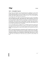
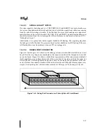
Figure 16-5 and Figure 16-6 show how the debug port connector should be installed on a circuit
board. Note the way the pins are numbered on the connector and how the through holes are laid
out on the board. Figure 16-6 shows a dotted line representation of the connector and behind it
the through holes as seen from the top side of the circuit board (the side on which the connector
will be placed). The through holes are shown so that you can match the pin numbers of the con-
nector to where the connector leads will fall on the circuit board. Although this may appear very
simple, it is surprising how often mistakes are made in this aspect of the debug port layout.
Figure 16-5. Debug Port Connector on Primary Side of Circuit Board
Summary of Contents for Pentium Pro Family
Page 17: ...1 Component Introduction ...
Page 26: ...2 Pentium Pro Processor Architecture Overview ...
Page 27: ......
Page 36: ...3 Bus Overview ...
Page 62: ...4 Bus Protocol ...
Page 105: ...5 Bus Transactions and Operations ...
Page 126: ...6 Range Registers ...
Page 131: ...7 Cache Protocol ...
Page 135: ...8 Data Integrity ...
Page 148: ...9 Configuration ...
Page 161: ...10 Pentium Pro Processor Test Access Port TAP ...
Page 172: ...11 Electrical Specifications ...
Page 201: ...12 GTL Interface Specification ...
Page 229: ...13 3 3V Tolerant Signal Quality Specifications ...
Page 233: ...14 Thermal Specifications ...
Page 239: ...15 Mechanical Specifications ...
Page 241: ...15 2 MECHANICAL SPECIFICATIONS s Figure 15 1 Package Dimensions Bottom View ...
Page 252: ...16 Tools ...
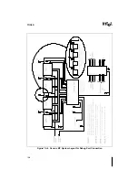
Page 260: ...16 8 TOOLS Figure 16 4 Generic MP System Layout for Debug Port Connection ...
Page 264: ...17 OverDrive Processor Socket Specification ...
Page 290: ...A Signals Reference ...
Page 320: ...Index ...
Page 328: ......


