17-5
OVERDRIVE® PROCESSOR SOCKET SPECIFICATION
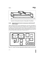
“Keep out zones,” also shown in Figure 17-4, have been established around the heat sink clip
attachment tabs to prevent damage to surface mounted components during clip installation and
removal. The keep out zones extend upwards from the surface of the motherboard to the top of
the heat sink. The lateral limits of the keep out zones extend 0.1 inch from the perimeter of each
tab.
Immovable objects must not be located less than 1.85 inches above the seating plane of the ZIF
socket. Removable objects must also not be located less than the 1.85 inches above the seating
plane of the ZIF socket required for the processor and fan/heatsink. These requirements also ap-
ply to the area above the cam shelf.
As shown in Figure 17-4 it is acceptable to allow any device (i.e. add-in cards, surface mount
device, chassis etc.) to enter within the free space distance of 0.2" from the chip package if it is
not taller than the level of the heat sink base. In other words, if a component is taller than height
'B', it cannot be closer to the chip package than distance 'A'. This applies to all four sides of the
chip package (the handle side of the ZIF socket will generally meet this specification since its
width is typically larger than distance 'A' (0.2")).
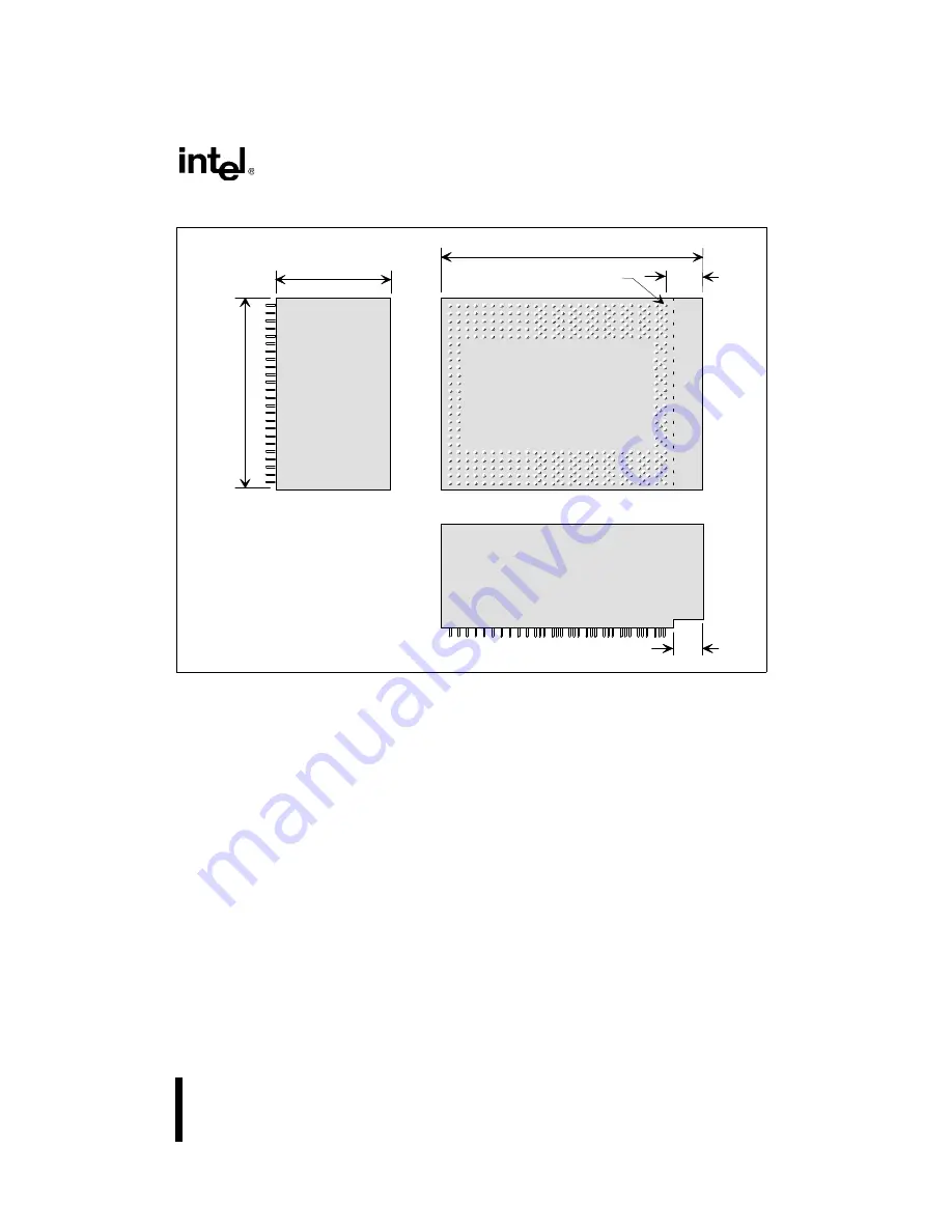
Figure 17-3. OverDrive
®
Processor Envelope Dimensions
OverDri
2.46"
3.23"
0.58"
0.50"
1.45"
TO P VIE W
E ND V IE W
S ID E V IEW
P in A 1
KEEP O UT ZO NES
NOT SHOW N
Summary of Contents for Pentium Pro Family
Page 17: ...1 Component Introduction ...
Page 26: ...2 Pentium Pro Processor Architecture Overview ...
Page 27: ......
Page 36: ...3 Bus Overview ...
Page 62: ...4 Bus Protocol ...
Page 105: ...5 Bus Transactions and Operations ...
Page 126: ...6 Range Registers ...
Page 131: ...7 Cache Protocol ...
Page 135: ...8 Data Integrity ...
Page 148: ...9 Configuration ...
Page 161: ...10 Pentium Pro Processor Test Access Port TAP ...
Page 172: ...11 Electrical Specifications ...
Page 201: ...12 GTL Interface Specification ...
Page 229: ...13 3 3V Tolerant Signal Quality Specifications ...
Page 233: ...14 Thermal Specifications ...
Page 239: ...15 Mechanical Specifications ...
Page 241: ...15 2 MECHANICAL SPECIFICATIONS s Figure 15 1 Package Dimensions Bottom View ...
Page 252: ...16 Tools ...
Page 260: ...16 8 TOOLS Figure 16 4 Generic MP System Layout for Debug Port Connection ...
Page 264: ...17 OverDrive Processor Socket Specification ...
Page 290: ...A Signals Reference ...
Page 320: ...Index ...
Page 328: ......

