4-14
BUS PROTOCOL
Since agent 1 observed active BPRI# in T12, it guarantees no new request generation beginning
T13. In T13, the priority agent deasserts BPRI#. In T15, three clocks from the previous request
and at least two clocks from BPRI# deassertion agent 1, the current symmetric owner issues
request 1a.
4.1.4.8.
BNR# SAMPLING
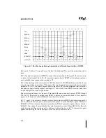
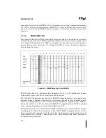
This section illustrates how BNR# is sampled by all agents, and how the stall protocol is imple-
mented. Figure 4-9 illustrates BNR# sampling as it begins after the processor is brought out of
reset. Figure 4-10 illustrates how BNR# is sampled once the stall protocol state machine
reaches the free state. Section 4.1.3.2., “Request Stall Protocol” may be useful as reference
when reading this section.
RESET# is asserted in T1, and observed by all agents in T2. In T3 or T4, BNR# must be deas-
serted and the request stall state is initialized to the stalled state.
In T5, RESET# is driven inactive, and in T6, RESET# is sampled inactive. Any agent that re-
quires more time to initialize its bus unit logic after reset is allowed to delay transaction gener-
ation by asserting BNR# in T7. In T7, the clock after RESET# is sampled inactive, BNR# is
driven to a valid level. In T8, two clocks after RESET# is sampled inactive, BNR# is sampled
active, causing the processor to remain in the stalled state in T9.
Because the processor is in the stalled state, BNR# is sampled every 2 clocks. BNR# is sampled
asserted again in T10, so the state remains stalled. In T12, BNR# is sampled inactive. In T13,
the request stall state transitions to the throttled state. One transaction can be issued to the bus
in the throttled state, so ADS# is driven active in T13. In the throttled state, BNR# continues to
be sampled every other clock.
Figure 4-9. BNR# Sampling After RESET#
CLK
RESET#
BINIT#
ADS#
BNR#
1
2
3
4
5
6
7
8
9
10
11
12
13
14
15
16
-
-
S
S
S
S
S
S
S
S
S
S
T
T
S
S
{request stall
AAAA
AAAA
AAAA
AAAA
AAAA
AAAA
AAAA
AAAA
AAAA
AAAA
AAAA
AAAA
AAAA
AAAA
AAAA
AAAA
AAAA
AAAA
AAAA
AAAA
AAAA
AAAA
AAAA
AAAA
AAAA
AAAA
AAAA
AAAA
AAAA
AAAA
AAAA
AAAA
AAAA
AAAA
AAAA
AAAA
AAAA
AAAA
AAAA
AAAA
AAAA
AAAA
AAAA
state}
17
18
19
T
T
F
Summary of Contents for Pentium Pro Family
Page 17: ...1 Component Introduction ...
Page 26: ...2 Pentium Pro Processor Architecture Overview ...
Page 27: ......
Page 36: ...3 Bus Overview ...
Page 62: ...4 Bus Protocol ...
Page 105: ...5 Bus Transactions and Operations ...
Page 126: ...6 Range Registers ...
Page 131: ...7 Cache Protocol ...
Page 135: ...8 Data Integrity ...
Page 148: ...9 Configuration ...
Page 161: ...10 Pentium Pro Processor Test Access Port TAP ...
Page 172: ...11 Electrical Specifications ...
Page 201: ...12 GTL Interface Specification ...
Page 229: ...13 3 3V Tolerant Signal Quality Specifications ...
Page 233: ...14 Thermal Specifications ...
Page 239: ...15 Mechanical Specifications ...
Page 241: ...15 2 MECHANICAL SPECIFICATIONS s Figure 15 1 Package Dimensions Bottom View ...
Page 252: ...16 Tools ...
Page 260: ...16 8 TOOLS Figure 16 4 Generic MP System Layout for Debug Port Connection ...
Page 264: ...17 OverDrive Processor Socket Specification ...
Page 290: ...A Signals Reference ...
Page 320: ...Index ...
Page 328: ......

