


Chapter 2 Hardware Configuration
Page: 2-12
PMB-601LF USER
′
S MANUAL
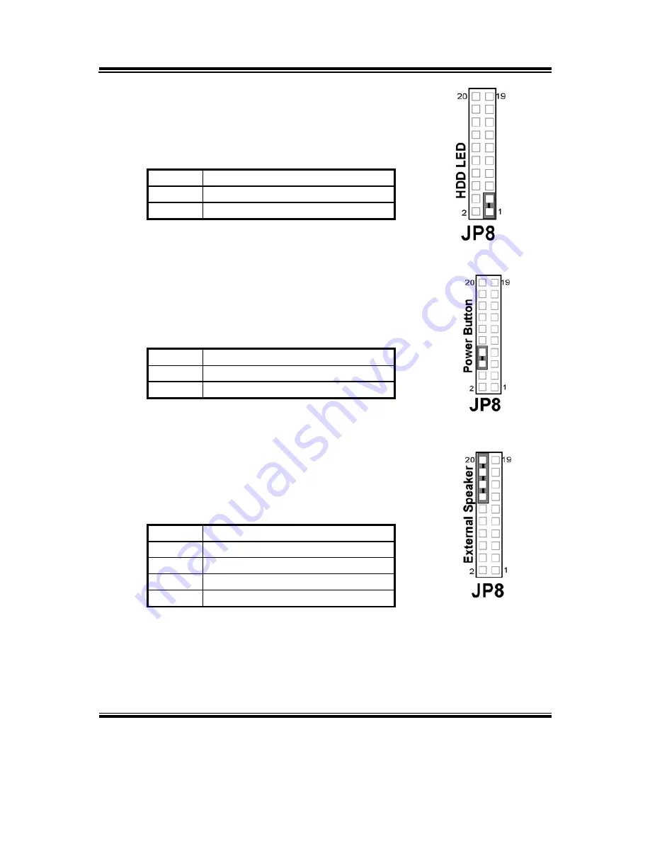
2-10. HARD DISK DRIVE LED CONNECTOR
JP8 (1, 3) :
Hard Disk Drive LED Connector
The pin assignment is as follows :
PIN ASSIGNMENT
1
3 HD_LED-
2-11. ATX POWER BUTTON
JP8 (6, 8) :
ATX Power Button
The pin assignment is as follows :
PIN ASSIGNMENT
6 PWRBTNSW
8 GND
2-12. EXTERNAL SPEAKER CONNECTOR
JP8 (14, 16, 18, 20) :
External Speaker Connector
The pin assignment is as follows :
PIN ASSIGNMENT
14 SPK_VCC
16 SPEAKER
SIGNAL
18 SPEAKER
SIGNAL
20 SPEAKER
SIGNAL


