True Scale Fabric Adapter Hardware
July 2015
Installation Guide
Order Number: G91929004US
17
Adapter Hardware
into the slot. Be careful not to push, grab, or put pressure on any other part of the
card, and avoid touching any of the components.
8. Secure the face plate to the chassis. The Intel
®
adapter has a screw hole on the
side of the face plate that can be attached to the chassis with a retention screw.
The securing method may vary depending on the chassis manufacturer. Refer to
the system documentation for information about mounting details such as
mounting holes, and screws to secure the card or other brackets.
Next, install the cables, as described in
“Cabling the Adapter to the Switch” on page 17
.
Then test your installation by powering up the system (see
3.5
Switch Configuration and Monitoring
The Intel interconnect is designed to work with all InfiniBand
*
-compliant switches, such
as the the Intel
®
12000 series. Follow the applicable switch documentation for
installing and configuring your switches.
3.6
Cabling the Adapter to the Switch
Follow the recommendations of your cable vendor for cable management and proper
bend radius.
The QLE7340 and QLE7342 are cabled the same way.
To install the cables:
1. Check that you have removed the protector plugs from the cable connector ends.
2. Different vendor cables might have different latch mechanisms. Determine if your
cable has a spring-loaded latch mechanism.
• If your cable is spring-loaded, grasp the metal shell and pull on the plastic latch to
release the cable. To insert, push and the cable snaps into place. You will hear a
short “click” sound from the cable connector when it snaps in.
• If your cable latch mechanism is not spring-loaded, push on the metal case, then
push the plastic latch to lock the cable in place.
3. The InfiniBand
*
cables are symmetric; either end can be plugged into the switch.
Connect the cable to the connector on the Intel
®
QLE7340 and QLE7342. Depress
the side latches of the cable when connecting. (On some cables, this latch is
located at the top of the cable connector.) Make sure the lanyard handle on the
cable connector is slid forward toward the card connector until fully engaged.
4. Connect the other end of the cable to the switch.
3.7
Completing the Installation
To complete the hardware installation:
1. Complete any other installation steps for other components.
2. Replace the cover plate and back panel.
3. Verify that the power cable is properly connected.
4. Turn on the power supply and boot the system normally.
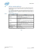
5. Watch the LED indicators. The LEDs will flash only once, briefly, at power-up. The
LEDs are functional only after the True Scale software has been installed, the driver
has been loaded, and the system is connected to an InfiniBand
*
switch. To use the
LEDs to check the state of the adapter, see
“LED Link and Data Indicators”
.

