Intel® Server Board S1200SP Family Technical Product Specification
xii
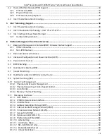
List of Tables
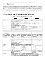
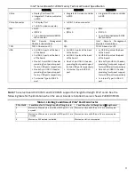
Server Board S1200SP Feature Set
Table 2. Limiting Conditions of PCIe* Card Form Factor
Table 3. UDIMM Support Guidelines
Server Board S1200SP DIMM Nomenclature
Server Board S1200SP DIMM Maximum Configuration
................................................................................ 20
Table 6. Intel® C230 Series Chipset Features
Table 7. External RJ45 NIC Port LED Definition
Table 8. Onboard Video Resolution and Refresh Rate (Hz)
Table 9. TPM Setup Utility – Security Configuration Screen Fields
...................................................................................... 36
Intelligent Power Node Manager
Intelligent Power Node Manager Capabilities and Features (SPS 4.x)
...................................................... 40
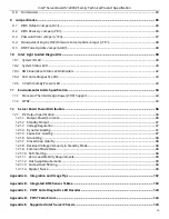
Table 12. Basic and Advanced Features
Table 14. Power Control Initiators
Table 15. Messaging Interfaces
Table 16. Factory Configured PEF Table Entries
Table 18. Additional Diagnostics on Error
Table 19. Intel® Remote Management Module 4 (RMM4) Options
........................................................................................ 66
Table 20. Board Connector Matrix
Table 21. Main Power Connector Pin-out (J9H1)
Table 22. CPU Power Connector Pin-out (J9B1)
Table 23. PMBUS SSI Connector Pin-out (J9F1)
Table 24. Battery Holder (BT2F1)
Table 25. Stacked connector of USB 3.0+ dedicated RJ45 Management Port Pin-out (JA5A1)
....................................... 72
RMM4 – Lite Connector Pin-out (J3B1)
Table 27. TPM Connector Pin-out (J8K1)
ESRT2 RAID Upgrade Key Connector Pin-out (J9K1)
.................................................................................. 73
Table 29. HSBP SMBUS Header Pin-out (J3K3)
Table 30. Chassis Intrusion Header Pin-out (J9B2)
Table 31. SATA SGPIO Header Pin-out (J2K5, J2K6)
Table 32. IPMB Connector Pin-out (J1G2)
Table 33. Front Panel 24-pin Connector Pin-out (J9E1)
Table 34. Power/Sleep LED Functional States
Table 35. NMI Signal Generation and Event Logging
Table 36. VGA Connector Pin-out (J8A1)
Table 37. Display Port Connector Pin-out (J4A1)
Table 38. SATA/SATADOM capable Connector Pin-out (J1K4, J1K1, J1K5, J1K2, J2K4, J2K3, J2K1, J2K2)
Table 39. M.2 SATA Connector Pinout
Table 40. Internal 9-pin Serial Header Pin-out (J9A1)
Table 41. USB 2.0 FP Header (J1J2)
Table 42. USB3.0 FP Header (J1J1)
Table 43. USB 2.0 Connector (Rear IO) (J6A1)
Table 44. Internal Type A USB Port Pin-out (J1K3)
Table 45. I/O Module Connector Pin-out (J1C1)
Table 45. I/O Module Connector Pin-out (J4J1)
Table 46. NIC Connector Pin-out (JA7A1, J6A2)
Table 47. SSI 4-pin Fan Header Pin-out (J3K2, J8B1, J7K1, J8K2, J8K3)
............................................................................ 84
Table 48. Server Board Jumpers (J4B1, J1F1, J1F4, J7B1, J4C1)
......................................................................................... 86
Table 49. System Status LED State Definitions
Table 50. BMC Boot/Reset Status LED Indicators
Summary of Contents for S1200SPL
Page 3: ......


