background image

Intel® Server Board S1200SP Family Technical Product Specification 


125 

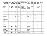
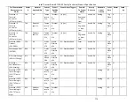
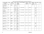
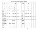
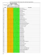
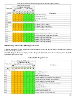
Checkpoint 

Diagnostic LED Decoder 

Description 

1 = LED On, 0 = LED Off 

Upper Nibble 

Lower Nibble 

MSB 


LSB 

8h  4h  2h  1h  8h  4h  2h  1h 

LED 

#7  #6  #5  #4  #3  #2  #1  #0 

02h = Violation of DIMM population rules. 
03h = The 3rd DIMM slot cannot be populated when QR DIMMs are 
installed. 
04h = UDIMMs are not supported in the 3rd DIMM slot. 
05h = Unsupported DIMM Voltage. 

EFh 

Indicates a CLTT table structure error 


Summary of Contents for S1200SPL

Page 1: ...S1200SP Product Family Technical Product Specification A document providing an overview of product features functions architecture and support specifications Revision 1 7 February 2018 Intel Server Products and Solutions ...

Page 2: ...Intel Server Board S1200SP Family Technical Product Specification This page is intentionally left blank ...

Page 3: ......

Page 4: ... Enterprise M 2 support January 2017 1 3 Added E3 1200 V6 processors support March 2017 1 4 Added Intel SGX for E3 1200 V6 November 2017 1 5 Updated Table 62 POST Progress Codes Changed 34h instead of 32h CPU Init December 2017 1 6 Replace RAID key name RKSATA8R5 with RKSATA4R5 in sections 2 1 and 3 4 3 Added commercial name AXXTPMSPE6 on TPM2 0 sections 4 3 and 8 3 2 February 2018 1 7 Modified no...

Page 5: ...mance course of dealing or usage in trade This document contains information on products services and or processes in development All information provided here is subject to change without notice Contact your Intel representative to obtain the latest TPS The products and services described may contain defects or errors known as errata which may cause deviations from published specifications Curren...

Page 6: ...21 3 3 4 Processor Integrated I O Module IIO 22 3 3 5 Intel Integrated RAID Option 22 3 3 6 Optional I O Module Support 23 3 3 7 Intel I O Acceleration Technolgy 2 Intel I O AT2 23 3 4 Intel C230 Series Chipset PCH Functional Overview 23 3 4 1 Digital Media Interface DMI 24 3 4 2 PCI Express Interface 24 3 4 3 Serial ATA SATA Controller 24 3 4 4 Low Pin Count LPC Interface 26 3 4 5 Serial Peripher...

Page 7: ... Power Interface ACPI 44 6 4 Power Control Sources 45 6 5 BMC Watchdog 45 6 6 Fault Resilient Booting FRB 46 6 7 Sensor Monitoring 47 6 8 Field Replaceable Unit FRU Inventory Device 47 6 9 System Event Log SEL 47 6 10 System Fan Management 47 6 10 1 Thermal and Acoustic Management 48 6 10 2 Thermal Sensor Input to Fan Speed Control 48 6 10 3 Auto Profiles 49 6 10 4 Memory Thermal Throttling 50 6 1...

Page 8: ...71 8 3 System Management Headers 72 8 3 1 Intel Remote Management Module 4 Lite Connector 72 8 3 2 TPM Connector 73 8 3 3 Intel ESRT2 RAID Upgrade Key Connector 73 8 3 4 HSBP SMBUS Header 73 8 3 5 Chassis Intrusion Header 74 8 3 6 SATA SGPIO Header 74 8 3 7 IPMB Connector 74 8 4 Front Panel Connector 74 8 4 1 Power Sleep Button and LED Support 75 8 4 2 System ID Button and LED Support 75 8 4 3 Sys...

Page 9: ... Thermal Design Power TDP Support 94 11 2 MTBF 95 12 Server Board Power Distribution 96 12 1 DC Output Specification 96 12 1 1 Output Power Currents 96 12 1 2 Standby Output 97 12 1 3 Voltage Regulation 97 12 1 4 Dynamic Loading 97 12 1 5 Capacitive Loading 97 12 1 6 Grounding 98 12 1 7 Closed loop stability 98 12 1 8 Residual Voltage Immunity in Standby Mode 98 12 1 9 Common Mode Noise 98 12 1 10...

Page 10: ...Intel Server Board S1200SP Family Technical Product Specification x Glossary 130 Reference Documents 133 ...

Page 11: ...igure 12 Intel Server Board S1200SPS Rear I O Layout 14 Figure 13 Intel Server Board S1200SPO Rear I O Layout 14 Figure 13 Intel Server Board S1200SP Functional Block Diagram 15 Figure 14 Intel Server Board S1200SP DIMM Slot Layout 20 Figure 15 Intel Server Board S1200SP Series USB Mapping Diagram 26 Figure 16 Integrated BMC Functional Block Diagram 30 Figure 17 Setup Utility TPM Configuration Scr...

Page 12: ... Stacked connector of USB 3 0 dedicated RJ45 Management Port Pin out JA5A1 72 Table 26 Intel RMM4 Lite Connector Pin out J3B1 73 Table 27 TPM Connector Pin out J8K1 73 Table 28 Intel ESRT2 RAID Upgrade Key Connector Pin out J9K1 73 Table 29 HSBP SMBUS Header Pin out J3K3 73 Table 30 Chassis Intrusion Header Pin out J9B2 74 Table 31 SATA SGPIO Header Pin out J2K5 J2K6 74 Table 32 IPMB Connector Pin...

Page 13: ...Table 57 Ripples and Noise 99 Table 58 Timing Requirements 100 Table 59 Integrated BMC Core Sensors 105 Table 60 POST Progress Code LED Example 121 Table 61 POST Progress Codes 121 Table 62 MRC Progress Codes 123 Table 63 POST Progress LED Codes 124 Table 64 POST Error Codes and Messages 126 Table 65 POST Error Beep Codes 128 Table 66 Integrated BMC Beep Codes 128 Table 67 Compatible Intel Server ...

Page 14: ...Intel Server Board S1200SP Family Technical Product Specification xiv This page intentionally left blank ...

Page 15: ...umper Blocks Chapter 10 Intel Light Guided Diagnostics Chapter 11 Environmental Limits Specifications Chapter 12 Server Board Power Distribution Appendix A Integration and Usage Tips Appendix B Integrated BMC Sensor Tables Appendix C POST Code Diagnostic LED Decoder Appendix D POST Code Errors Appendix E Supported Intel Server Chassis Glossary Reference Documents 1 2 Server Board Use Disclaimer In...

Page 16: ... MT s Unbuffered UDIMM DDR4 ECC memory Max Memory 64GB Add in PCI Express Slots and Module Connectors Number 4 See Note 3 See Note 3 Add in PCI Express Slots and Module Connectors Configuration PCI Express Gen3 x8 electrical with x16 physical connector from processor PCI Express Gen3 x8 electrical with x16 physical connector from processor PCI Express Gen3 x 8 electrical with x16 physical connecto...

Page 17: ...k of the board 2x USB 2 0 ports at the back of the board One 2x5 pin USB 2 0 header providing front panel support for two USB ports respectively 1x internal Type A USB 2 0 port 2x USB 3 0 ports at the back of the board 2x USB 2 0 ports at the back of the board One 2x10 pin USB 3 0 header providing front panel support for two USB ports respectively One 2x5 pin USB 2 0 header providing front panel s...

Page 18: ...Intel Server Board S1200SP Family Technical Product Specification 4 2 2 Server Board Layout Figure 1 Intel Server Board S1200SP Layout S1200SPL ...

Page 19: ...oard S1200SP Family Technical Product Specification 5 2 2 1 Server Board Connector and Component Layout Each connector and major component is identified in the figure below Figure 2 Intel Server Board S1200SPL Layout ...

Page 20: ...Intel Server Board S1200SP Family Technical Product Specification 6 Figure 3 Intel Server Board S1200SPS Layout ...

Page 21: ...Intel Server Board S1200SP Family Technical Product Specification 7 Figure 4 Intel Server Board S1200SPO Layout ...

Page 22: ...Intel Server Board S1200SP Family Technical Product Specification 8 2 2 2 Server Board Mechanical Drawings Figure 5 Intel Server Board S1200SP Mounting Hole Locations ...

Page 23: ...Intel Server Board S1200SP Family Technical Product Specification 9 Figure 6 Intel Server Board S1200SP Mounting Hole Locations continued ...

Page 24: ...Intel Server Board S1200SP Family Technical Product Specification 10 Figure 7 Intel Server Board S1200SP Major Connector Pin 1 Locations ...

Page 25: ...Intel Server Board S1200SP Family Technical Product Specification 11 Figure 8 Intel Server Board S1200SP Major Connector Pin 1 Locations continued ...

Page 26: ...Intel Server Board S1200SP Family Technical Product Specification 12 Figure 9 Intel Server Board S1200SP Primary Side Keepout Zone ...

Page 27: ...Intel Server Board S1200SP Family Technical Product Specification 13 Figure 10 Intel Server Board S1200SP Second Side Keepout Zone ...

Page 28: ...erver Board Rear I O Layout The following drawing shows the layout of the rear I O components for the server boards Figure 11 Intel Server Board S1200SPL Rear I O Layout Figure 12 Intel Server Board S1200SPS Rear I O Layout Figure 13 Intel Server Board S1200SPO Rear I O Layout ...

Page 29: ...USB 1 1 USB 2 0 14 6 HDD 8 SATA 6G Back Panel USB 3 0 LPC TPM Header PCIe Gen3 x4 P1 P4 2 P13 16 17 20 P1 P2 Front Panel USB 3 0 Header SAS Module Silver Pass Block Diagram CPLD Phy GbE Mgmt LAN Back Panel RGMII Misc VRs VCC 0 2 Vddq Vtt VCCio VCCsa VDDq Vtt Vpp Slot 6 x16 connector x8 connectors Resister Switch Slot 5 Slot 4 LC SE SKU x8 connectors PCIe Gen3 x 1 P10 P1 P5 P3 P4 2 P2 P4 USB Back P...

Page 30: ...oduct family several key system components including the CPU Integrated Memory Controller IMC and Integrated IO Module IIO have been combined into a single processor package and feature up to 20 lanes of Gen 3 PCI Express links The following sections provide an overview of the key processor features and functions that help to define the performance and architecture of the server board For more com...

Page 31: ...nables trusted memory regions trusted enclaves Isolates enclaves from malware and privileged software attacks Processor controls access prevents intrusion encrypts transported stored data Limitations Intel Server Board S1200SP family firmware does not support monotonic counters and trusted time features Some SGX use models such as distributed ledger with Proof of Elapsed Time PoET consensus algori...

Page 32: ...stalled Channel A Slot1 is DIMM_A1 Channel A Slot2 is DIMM_A2 Channel B Slot1 is DIMM_B1 Channel B Slot2 is DIMM_B2 3 3 1 Supported Memory Single Ranked x8 unbuffered ECC Dual Ranked x8 unbuffered ECC Table 3 UDIMM Support Guidelines Ranks Per DIMM and Data Width Memory Capacity Per DIMM Speed MT s and Voltage Validated by Slot per Channel SPC and DIMM Per Channel DPC 2 Slots per Channel 1DPC 2DPC...

Page 33: ...channels that belong to processor socket The silk screened DIMM slot identifiers on the board provide information about the channel For example DIMM_A1 is the first slot on Channel A on processor Channel A and Channel B are independent and are not required to have the same number of DIMMs installed Either channel may be used for a single DIMM configuration When only one memory channel is populated...

Page 34: ...isplays the Effective Memory of the system in the BIOS setup The term Effective Memory refers to the total size of all DDR4 DIMMs that are active not disabled The BIOS provides the total memory of the system in the main page of the BIOS setup This total is the same as the amount described by the first bullet above If Display Logo is disabled the BIOS displays the total system memory on the diagnos...

Page 35: ...Intel Server Board S1200SP product family board is set at 10 events When the 10th CE occurs a single Correctable Error event is logged 3 3 3 Post Error Codes The range 0xE0 0xEF of POST codes is used for memory errors in early POST In late POST this same range of POST code values is used for reporting other system errors 0xE8 No Usable Memory Error If no usable memory is available the BIOS emits a...

Page 36: ...ed I O module provides features traditionally supported through chipset components The integrated I O module provides the following features PCI Express Interfaces The integrated I O module incorporates the PCI Express interface and supports up to 16 lanes of PCI Express Following are key attributes of the PCI Express interface Gen3 speeds at 8 GT s no 8b 10b encoding Can operate at 2 5 GT s 5 GT ...

Page 37: ...dule attaches to a high density 80 pin connectors on the server board J1C1 labeled I O_MOD and is supported by up to x8 PCIe Gen 3 signals from IIO module of the processor For supported I O Modules refer to the document Intel Server Boards S1200SP Configuration Guide and Spares Accessories List 3 3 7 Intel I O Acceleration Technolgy 2 Intel I O AT2 Intel I O AT2 is not supported 3 3 7 1 Direct Cac...

Page 38: ...egacy software to operate normally 3 4 2 PCI Express Interface The Intel C230 series chipset provides up to 20 PCI Express Root Ports supporting the PCI Express Base Specification Revision 3 0 Each Root Port x1 lane supports up to 8 Gb s bandwidth in each direction 16 Gb s concurrent On the Intel Server Board S1200SPL and S1200SPO PCI Express Root Ports 1 4 are configured to support one Gen3 x4 po...

Page 39: ...ble SW RAID and select which embedded software RAID option to use 3 4 3 1 Intel Rapid Storage Technology Enterprise The Intel C230 series chipset provides support for Intel Rapid Storage Technology enterprise providing both AHCI see above for details on AHCI and integrated RAID functionality The industry leading RAID capability provides high performance RAID 0 1 5 and 10 functionality on up to 8 S...

Page 40: ...pset implements an SPI Interface as an alternative interface for the BIOS flash device 3 4 6 Universal Serial Bus USB Controller The Intel C230 series chipset contains an eXtensible Host Controller Interface xHCI host controller which supports up to fourteen USB 2 0 ports and up to six USB 3 0 ports This controller allows data transfers of up to 5Gb s The controller supports SuperSpeed SS high spe...

Page 41: ...ports and searches for a keyboard and or a mouse on the USB hub and then enables the devices that are recognized 3 4 7 Gigabit Ethernet Controller Network connectivity is provided by means of two onboard Intel Ethernet Controller I210 providing up to two 10 100 1000 Mb Ethernet ports The Intel Ethernet Controller I210 is single compact low power components that offer a fully integrated Gigabit Eth...

Page 42: ...address NIC 1 MAC address 1 for OS usage BMC LAN channel 1 MAC address NIC1 MAC address 2 BMC LAN channel 2 MAC address NIC1 MAC address 3 3 4 8 Serial Ports The server board provides a nine pin internal DH 10 serial header You can use a standard DH 10 to DB9 cable to direct serial A port to the rear of a chassis 3 4 9 KVM Serial Over LAN SOL Function These functions support redirection of keyboar...

Page 43: ...s of technology components that support the virtualization of platforms based on Intel Architecture Processors Intel VT d Technology enables multiple operating systems and applications to run in independent partitions A partition behaves like a Virtual Machine VM and provides isolation and protection across partitions Each partition is allocated its own subset of host physical memory 3 5 Integrate...

Page 44: ... Boot Flash USB to Host Integrated BMC Pilot 3 Block Diagram System Wakeup Control KCS BT Mailboxes GPIO SGPIO UART 2 LPC Interface ARM926EJ S 16K D I Cache 400MHz Interrupt Controller Fan Tach 16 PWM 8 ADC 16 PECI3 0 10 100 1000 Ethernet MAC with RMII RGMII 2 USB 1 1 USB 2 0 SPI Flash BOOT BKUP DDR II III 16 bit Memory Controller JTAG Debug Port JTAG Master LPC Master LPC Master BMC Data Flash RM...

Page 45: ...hese channels support can be enabled for IPMI over LAN and DHCP For security reasons embedded LAN channels have the following default settings IP Address Static All users disabled 3 5 3 Graphics Controller and Video Support The integrated graphics controller provides support for the following features as implemented on the server board Integrated Graphics Core with 2D Hardware accelerator DDR 3 me...

Page 46: ... Supported Note Video resolutions at 1600x1200 and higher are only supported through the external video connector located on the rear I O section of the server board On Intel Server Board S1200SPL the display port is supported from the processor A display port to VGA convertor and a VGA mux are implemented to enable VGA output from processor graphics Users can set Primary Display option in BIOS to...

Page 47: ...e accepted Once set a password can be cleared by changing it to a null string This requires the Administrator password and must be done through BIOS Setup or other explicit means of changing the passwords Clearing the Administrator password will also clear the User password Alternatively the passwords can be cleared by using the Password Clear jumper if necessary Resetting the BIOS configuration s...

Page 48: ... boot process to create a system fingerprint This unique fingerprint remains the same unless the pre boot environment is tampered with Therefore it is used to compare to future measurements to verify the integrity of the boot process After the system BIOS completes the measurement of its boot process it hands off control to the operating system loader and in turn to the operating system If the ope...

Page 49: ...M Setup the operator can turn ON or OFF TPM functionality and clear the TPM ownership contents After the requested TPM BIOS Setup operation is carried out the option reverts to No Operation The BIOS TPM Setup also displays the current state of the TPM whether TPM is enabled or disabled and activated or deactivated Note that while using TPM a TPM enabled operating system or application may change t...

Page 50: ...ity Security Configuration Screen Fields Setup Item Options Help Text Comments TPM State Enabled and Activated Enabled and Deactivated Disabled and Activated Disabled and Deactivated Information only Shows the current TPM device state A disabled TPM device will not execute commands that use TPM functions and TPM security operations will not be available An enabled and deactivated TPM is in the sam...

Page 51: ...vides a general purpose safer computing environment capable of running a wide variety of operating systems and applications to increase the confidentiality and integrity of sensitive information without compromising the usability of the platform Intel Trusted Execution Technology requires a computer system with Intel Virtualization Technology enabled both VT x and VT d an Intel Trusted Execution T...

Page 52: ... hardware resources Each software environment may consist of OS and applications The Intel Virtualization Technology features can be enabled or disabled in the BIOS setup The default behavior is disabled Intel VT d is supported jointly by the Intel Xeon Processor E3 1200 V5 and V6 Product Families and The Intel C230 series chipset Both support DMA remapping from inbound PCI Express memory Guest Ph...

Page 53: ...y the Intel C230 series chipset Management Engine ME and Intel Intelligent Power Node Manager NM technology The ME NM combination is a power and thermal control capability on the platform which exposes external interfaces that allow IT through external management software to query the ME about platform power capability and consumption thermal characteristics and specify policy directives for examp...

Page 54: ...he processor power consumption through processor P states and dynamic core allocation Core allocation at boot time Restrict the number of cores for OS VMM use by limiting how many cores are active at boot time After the cores are turned off the CPU will limit how many working cores are visible to BIOS and OS VMM The cores that are turned off cannot be turned on dynamically after the OS has started...

Page 55: ...e to the ME NM power limiting feature requires a means for the ME to monitor input power consumption for the platform This capability is generally provided by means of PMBus compliant power supplies although an alternative model using a simpler SMBus power monitoring device is possible there is potential loss in accuracy and responsiveness using non PMBus devices The NM SmaRT CLST feature requires...

Page 56: ...onents and options that may be installed 6 1 1 IPMI 2 0 Features Baseboard management controller BMC IPMI Watchdog timer Messaging support including command bridging and user session support Chassis device functionality including power reset control and BIOS boot flags support Event receiver device The BMC receives and processes events from other platform subsystems Field Replaceable Unit FRU inve...

Page 57: ... a command Power state retention Power fault analysis Intel Light Guided Diagnostics Power unit management Support for power unit sensor The BMC handles power good dropout conditions DIMM temperature monitoring New sensors and improved acoustic management using closed loop fan control algorithm taking into account DIMM temperature readings Address Resolution Protocol ARP The BMC sends and responds...

Page 58: ...with optional Intel Remote Management Module 4 Intel Intelligent Power Node Manager Support requires PMBus compliant power supply 6 3 Advanced Configuration and Power Interface ACPI The server board supports the following ACPI states Table 13 ACPI Power States State Supported Description S0 Yes Working The front panel power LED is on not controlled by the BMC The fans spin at the normal speed as d...

Page 59: ... are time critical in that failure to provide these functions in a timely manner can result in system or component damage Intel server board S1200SP introduces a BMC watchdog feature to provide a safe guard against this scenario by providing an automatic recovery mechanism It also can provide automatic recovery of functionality that has failed due to a fatal FW defect triggered by a rare sequence ...

Page 60: ...ault LEDs may not reflect BIOS detected errors 6 6 Fault Resilient Booting FRB Fault resilient booting FRB is a set of BIOS and BMC algorithms and hardware support that allow a multiprocessor system to boot even if the bootstrap processor BSP fails Only FRB2 is supported using watchdog timer commands FRB2 refers to the FRB algorithm that detects system failures during POST The BIOS uses the BMC wa...

Page 61: ...FRU devices throughout the server The FRU device ID mapping is defined in the Platform Specific Information The BMC controls the mapping of the FRU device ID to the physical device 6 9 System Event Log SEL The BMC implements the system event log as specified in the Intelligent Platform Management Interface Specification Version 2 0 The SEL is accessible regardless of the system power state through...

Page 62: ...configured as static fixed value or controlled by the state of one or more associated temperature sensors Hysteresis can be specified to minimize fan speed oscillation and to smooth fan speed transitions 6 10 1 Thermal and Acoustic Management This feature refers to enhanced fan management to keep the system optimally cooled while reducing the amount of noise generated by the system fans Aggressive...

Page 63: ...ucture that implements the resulting fan speeds Figure 19 Fan Speed Control Process 6 10 3 Auto Profiles PCSD board implements auto profile feature to improve upon previous platform configuration dependent FSC and maintain competitive acoustics within the market This feature is not available for third party customization BIOS and BMC will handshake to automatically understand configuration details...

Page 64: ...onfigured by BIOS MRC during POST The memory throttling is run as a closed loop system with the DIMM temperature sensors as the control input Otherwise the system does not change any of the throttling control registers in the embedded memory controller during runtime Intel Server Systems supporting the Intel Xeon processor E3 1200 V5 and V6 product family introduce a new type of CLTT which is refe...

Page 65: ...always Null blank and root respectively 2 User 2 root always has the administrator privilege level 3 All user passwords including passwords for 1 and 2 may be modified 4 User IDs 3 15 may be used freely with the condition that user names are unique Therefore no other users can be named Null root or any other existing user name 6 11 2 IPMB Communication Interface The IPMB communication interface us...

Page 66: ...band Interface NC SI manageability interface This provides a sideband high speed connection for manageability traffic to the BMC while still allowing for a simultaneous host access to the OS if desired The NC SI is a DMTF industry standard protocol for the side band management LAN interface This protocol provides a fast multi drop interface for management traffic The baseboard NICs are connected t...

Page 67: ...m a pool of up to 3 MAC addresses allocated specifically for manageability The server board has seven MAC addresses programmed at the factory MAC addresses are assigned as follows NIC 1 MAC address for OS usage NIC 2 MAC address NIC 1 MAC address 1 for OS usage BMC LAN channel 1 MAC address NIC1 MAC address 2 BMC LAN channel 2 MAC address NIC1 MAC address 3 BMC LAN channel 3 RMM4 MAC address NIC1 ...

Page 68: ...e lower unique portion comes from the BMC s channel MAC address The 6 byte MAC address is converted into an 8 byte value per the EUI 64 standard For example a MAC value of 00 15 17 FE 2F 62 converts into a EUI 64 value of 215 17ff fefe 2f62 If the BMC receives a Router Advertisement from a router at IP 1 2 3 4 1 with a prefix of 64 it would then generate for itself an IP of 1 2 3 4 215 17ff fefe 2...

Page 69: ...red The Set LAN Configuration Parameter command must be used to configure LAN configuration parameter 3 IP Address with an appropriate value The BIOS does not monitor the value of this parameter and it does not execute DHCP for the BMC under any circumstances regardless of the BMC configuration 6 11 3 5 2 Static LAN Configuration Parameters When the IP Address Configuration parameter is set to 01h...

Page 70: ...orted value will cause the BMC to stop the DHCP process The BMC uses the most recently obtained IP address until it is reconfigured If the physical LAN connection is lost that is the cable is unplugged the BMC will not re initiate the DHCP process when the connection is re established 6 11 3 5 4 DHCP related LAN Configuration Parameters Users may not change the following LAN parameters while the D...

Page 71: ...g the BMC over integrated NICs Echo request ping The BMC sends an Echo Reply Destination unreachable If message is associated with an active socket connection within the BMC the BMC closes the socket 6 11 6 Virtual Local Area Network VLAN The BMC supports VLAN as defined by IPMI 2 0 specifications VLAN is supported internally by the BMC not through switches VLAN provides a way of grouping a set of...

Page 72: ...l SSH Secure Shell SSH connections are supported for SMASH CLP sessions to the BMC There is a maximum of one SMASH CLP session allowed 6 11 8 Serial over LAN SOL 2 0 The BMC supports IPMI 2 0 SOL IPMI 2 0 introduced a standard serial over LAN feature This is implemented as a standard payload type 01h over RMCP Three commands are implemented for SOL 2 0 configuration Get SOL 2 0 Configuration Param...

Page 73: ...lowing PEF actions Power off Power cycle Reset OEM action Alerts The Diagnostic interrupt action is not supported 6 11 10 LAN Alerting The BMC supports sending embedded LAN alerts called SNMP PET Platform Event traps and SMTP email alerts The BMC supports a minimum of four LAN alert destinations 6 11 10 1 SNMP Platform Event Traps PETs This feature enables a target system to send SNMP traps to a d...

Page 74: ...t is syntax compatible but not considered fully compliant with the DMTF standards The SM CLP utilized by a remote user by connecting a remote system using one of the system NICs It is possible for third party management applications to create scripts using this CLP and execute them on server to retrieve information or perform management tasks such as reboot the server configure events and so on Th...

Page 75: ...resent all the Basic features to the users Power on off reset the server and view current power state Display BIOS BMC ME and SDR version information Display overall system health Configuration of various IPMI over LAN parameters for both IPV4 and IPV6 Configuration of alerting SNMP and SMTP Display system asset information for the product board and chassis Display of BMC owned sensors name status...

Page 76: ...ty to view and configure SOL log feature setting 6 11 14 Virtual Front Panel Virtual Front Panel is the module present as Virtual Front Panel on the left side in the embedded web server when remote Control tab is clicked Main Purpose of the Virtual Front Panel is to provide the front panel functionality virtually Virtual Front Panel VFP will mimic the status LED and Power LED status and Chassis ID...

Page 77: ...nts are saved in both hexadecimal and text format CPU memory register data Useful for diagnosing the cause of the following system errors CATERR ERR 2 SMI timeout PERR and SERR The debug data is saved and time stamped for the last 3 occurrences of the error conditions First 256 byte of PCI configuration space and the advanced error reporting registers Processor Machine Check Architecture registers...

Page 78: ...e BMC syslog messages and power supply black box data 6 11 15 1 Output Data Format The diagnostic feature outputs a password protected compressed HTML file containing specific BMC and system information This file is not intended for end customer usage This file is for customer support and engineering only 6 11 15 2 Output Data Availability The diagnostic data is available on demand from the embedd...

Page 79: ...atures in the BMC firmware DCMI 1 5 compliance Refer to DCMI 1 5 spec for details Only mandatory commands are supported No support for optional DCMI commands Optional power management and SEL roll over feature is not supported DCMI Asset tag is independent of baseboard FRU asset Tag 6 11 17 Lightweight Directory Access Protocol LDAP The Lightweight Directory Access Protocol LDAP is an application ...

Page 80: ... Lite key is installed at the following locations Figure 20 Intel RMM4 Lite Activation Key Installation 7 1 Dedicated Management Port The Intel server board S1200SPL and S1200SPO include a dedicated 1GbE RJ45 Management Port The management port is active with or without the RMM4 Lite key installed 7 2 Keyboard Video and Mouse KVM Redirection The BMC firmware supports keyboard video and mouse redir...

Page 81: ... redirection feature supports the following resolutions and refresh rates 640x480 at 60Hz 72Hz 75Hz 85Hz 100Hz 800x600 at 60Hz 72Hz 75Hz 85Hz 1024x768 at 60Hz 72Hz 75Hz 85Hz 1280x960 at 60Hz 1280x1024 at 60Hz 1600x1200 at 60Hz 1920x1080 1080p 1920x1200 WUXGA 1650x1080 WSXGA 7 2 1 Remote Console The Remote Console is the redirected screen keyboard and mouse of the remote host system To use the Remo...

Page 82: ...rt of the remote KVM session is required during a server reset or power on off A BMC reset for example due to a BMC Watchdog initiated reset or BMC reset after BMC FW update requires the session to be re established KVM sessions persist across system reset but not across an AC power loss 7 2 5 Usage As the server is powered up the remote KVM session displays the complete BIOS boot process The user...

Page 83: ... the server is powered off in standby mode No restart of the remote media session is required during a server reset or power on off A BMC reset for example due to a BMC reset after BMC FW update requires the session to be re established The mounted device is visible to and useable by managed system s OS and BIOS in both pre boot and post boot states The mounted device shows up in the BIOS boot ord...

Page 84: ...240 PCI Express x8 mechanical 2 J1B1 J2B1 Card edge 98 PCI Express x16 mechanical 1 J3B2 Card edge 164 RJ45 USB 3 0 connector 1 JA5A1 Connector 32 NIC connector 2 JA7A1 J6A2 Connector Intel RMM4 Lite 1 J3B1 Connector 8 SATA Key to enable ESRT2 RAID5 1 J9K1 Header 4 System fans 4 J3K2 J8K2 J8K3 J8B1 Header 4 CPU fan 1 J7K1 Header 4 Battery 1 BT2F1 Battery holder 2 VGA 1 J8A1 Connector 15 Display Po...

Page 85: ...ectors also exist One SSI compliant 2x4 pin power connector J9B1 to provide 12 V power to the CPU voltage regulators and memory One SSI compliant 1x5 pin connector J9F1 to provide I2C monitoring of the power supply The following tables define these connector pin outs Table 21 Main Power Connector Pin out J9H1 Pin IO Signal Name Pin IO Signal Name 1 PWR 3 3V 13 PWR 3 3V 2 PWR 3 3V 14 PWR 12V NA for...

Page 86: ...RMM4 Lite key installed The S1200SPS board does not support Intel RMM4 This server board does not support third party management cards Note This connector is not compatible with the previous generation Intel Remote Management Modules Intel RMM RMM2 RMM3 Table 25 Stacked connector of USB 3 0 dedicated RJ45 Management Port Pin out JA5A1 Pin IO Name Pin IO Name 1 PWR P5V_AUX 17 I USB3_TX_DN 2 IO USB2...

Page 87: ...L 6 I LPC_FRAME_N 7 PWR P3V3 8 GND GND 9 I RST_BMC_NIC_LRESET_LVC3_R_N 10 I CLK_33M_TPM_CONN 11 IO LPC_LAD 3 12 GND GND 13 GND GND 14 IO LPC_LAD 2 8 3 3 Intel ESRT2 RAID Upgrade Key Connector The server board provides one connector to support Intel ESRT2 RAID Upgrade Key The I Upgrade Key is a small PCB board that enables RAID 5 software stack of ESRT2 SW RAID The pin configuration of connector is...

Page 88: ...A SGPIO Header Two SATA SGPIO 5 pin headers are implemented on the Intel Server Board S1200SPL and S1200SPO one is for Port0 3 White and the other is for Port4 7 Black Table 31 SATA SGPIO Header Pin out J2K5 J2K6 Pin IO Signal Name 1 I SGPIO_CLOCK 2 I SGPIO_LOAD 3 GND GND 4 I SGPIO_DATAOUT 5 O SGPIO_DATAIN 8 3 7 IPMB Connector An IPMB header is provided on the baseboard to support connectivity wit...

Page 89: ... on or power off the system The power LED is a single color and is capable of supporting different indicator states as defined in the following table Table 34 Power Sleep LED Functional States State Power Mode LED Description Power off Non ACPI Off System power is off and the BIOS has not initialized the chipset Power on Non ACPI On System power is on S5 ACPI Off Mechanical is off and the operatin...

Page 90: ...t panel diagnostic interrupt button pressed X X Watchdog Timer pre timeout expiration with NMI diagnostic interrupt action X X 8 4 5 NIC Activity LED Support The Front Control Panel includes an activity LED indicator for each on board Network Interface Controller NIC When a network link is detected the LED will turn on solid The LED will blink once network activity occurs at a rate that is consist...

Page 91: ...ctor Pin out J4A1 Pin IO Signal Name Pin IO Signal Name 1 I DP_DDI_TX_DP0 2 GND GND 3 I DP_DDI_TX_DN0 4 I DP_DDI_TX_DP1 5 GND GND 6 I DP_DDI_TX_DN1 7 I DP_DDI_TX_DP2 8 GND GND 9 I DP_DDI_TX_DN2 10 I DP_DDI_TX_DP3 11 GND GND 12 I DP_DDI_TX_DN3 13 O FM_DP_DNG_DETECT 14 I PD_DP_CONFIG2 15 IO DP_AUX_DP 16 GND GND 17 IO DP_AUX_DN 18 O FM_DP_HPD_SINK 19 GND GND 20 PWR P3V3 8 5 3 SATA Connectors The Inte...

Page 92: ... GND MH2 PWR P5V For Apacer SATADOM GND For SATA 8 5 4 M 2 SATA Connector J2G1 The Intel Server Board S1200SPL and S1200SPO support one 22x42mm enterprise M 2 SATA SSD In order to use M 2 device a SATA cable need to be connected between any of the SATA connectors SATA 0 to SATA 7 recommend SATA 7 for better cable routing and the SATA connector black next to the jumpers See illustration below The c...

Page 93: ...al Port Connector The server board provides one internal 9 pin Serial header The following tables define the pin out Table 40 Internal 9 pin Serial Header Pin out J9A1 Pin IO Signal Name Pin IO Signal Name 1 O SPA_DCD 2 O SPA_DSR 3 O SPA_SIN_N 4 I SPA_RTS 5 I SPA_SOUT_N 6 O SPA_CTS 7 I SPA_DTR 8 O SPA_RI 9 GND GND ...

Page 94: ...ignal Name Pin IO Signal Name 1 PWR P5V_AUX 2 PWR P5V_AUX 3 IO USB_N 4 IO USB_N 5 IO USB_P 6 IO USB_P 7 GND GND 8 GND GND 9 NC Key Pin 10 NC NC Table 42 USB3 0 FP Header J1J1 Pin IO Signal Name Pin IO Signal Name 1 PWR P5V_AUX key NC KEY 2 O USB3_RX_DN 19 PWR P5V_AUX 3 O USB3_RX_DP 18 O USB3_RX_DN 4 GND GND 17 O USB3_RX_DP 5 I USB3_TX_DN 16 GND GND 6 I USB3_TX_DP 15 I USB3_TX_DN 7 GND GND 14 I USB...

Page 95: ...IOM REFCLK 0 29 GND GND 30 I rIOM REFCLK 0 31 I PCIe Gen3 Tn 7 32 GND GND 33 I PCIe Gen3 Tp 7 34 O PCIe Gen3 Rn 7 35 GND GND 36 O PCIe Gen3 Rp 7 37 I PCIe Gen3 Tn 6 38 GND GND 39 I PCIe Gen3 Tp 6 40 O PCIe Gen3 Rn 6 41 GND GND 42 O PCIe Gen3 Rp 6 43 I PCIe Gen3 Tn 5 44 GND GND 45 I PCIe Gen3 Tp 5 46 O PCIe Gen3 Rn 5 47 GND GND 48 O PCIe Gen3 Rp 5 49 I PCIe Gen3 Tn 4 50 GND GND 51 I PCIe Gen3 Tp 4 ...

Page 96: ...R 3 3V 76 PWR 12V 73 PWR 3 3V 74 PWR 12V 71 NC RSVD_SE 72 I FRU TEMP ADDR 0 69 GND GND 70 PWR 5V STBY 67 NC RSVD_DP 68 I FM_SAS_MODULE_EN_N 65 NC RSVD_DN 66 PWR 3 3V STBY 63 GND GND 64 O LED_HDD_N 61 NC RSVD_DP 62 O FM_SAS_PRESENT_N 59 NC RSVD_DN 60 O WAKE 57 GND GND 58 I PERST 55 I SMB CLK 56 GND GND 53 IO SMB DAT 54 I rSASm REFCLK 0 51 GND GND 52 I rSASm REFCLK 0 49 I PCIe Gen3 Tn 7 50 GND GND 4...

Page 97: ...tor Table 47 NIC Connector Pin out JA7A1 J6A2 Pin IO Signal Name R1 PWR NIC_TRCT R2 IO MDI_DP0 R3 IO MDI_DN0 R4 IO MDI_DP1 R5 IO MDI_DN1 R6 IO MDI_DP2 R7 IO MDI_DN2 R8 IO MDI_DP3 R9 IO MDI_DN3 R10 GND GND L1 IO LED2_1G_N L2 IO LED2_100M_N L3 O LED1_LINK_ACT_N L4 I P3V3 8 6 Fan Headers The server board provides five SSI compliant 4 pin fans to use as CPU and I O cooling fans 3 pin fans are supporte...

Page 98: ...ote Intel Corporation server boards support peripheral components and can contain a number of high density VLSI and power delivery components that need adequate airflow to cool Intel s own chassis are designed and tested to meet the intended thermal requirements of these components when the fully integrated system is used together It is the responsibility of the system integrator that chooses not ...

Page 99: ...identify the location of each jumper block and provides a description of their use The following symbol identifies Pin 1 on each jumper block on the silkscreen Figure 24 Jumper Blocks J4B1 J1F1 J1F4 J7B1 J4C1 Note 1 For safety purposes the power cord should be disconnected from a system before removing any system components or moving any of the on board jumper blocks 2 System Update and Recovery f...

Page 100: ...ult 2 3 BMC Firmware Force Update Mode Enabled 9 1 BIOS Default Jumper J4C1 1 This jumper resets BIOS Setup options to their default factory settings 2 Power down the server and unplug the power cords 3 Open the chassis and remove the Riser 2 assembly 4 Move BIOS DFLT jumper from the default pins 1 and 2 position to the Set BIOS Defaults position pins 2 and 3 5 Wait 5 seconds then move the jumper ...

Page 101: ... creates a security gap until passwords have been installed again through the BIOS Setup utility This is the only method by which the Administrator and User passwords can be cleared unconditionally Other than this jumper passwords can only be set or cleared by changing them explicitly in BIOS Setup or by similar means No method of resetting BIOS configuration settings to default values will affect...

Page 102: ...very mode 6 Boot to the EFI shell and update the ME firmware using the MEComplete cap file where ME revision number using the following command iflash32 u ni MEComplete cap 7 When update has successfully completed power off system 8 Remove AC power cords 9 Move ME FRC UPD jumper back to the default position Note If the ME FRC UPD jumper is moved with AC power applied the ME will not operate proper...

Page 103: ...e BMC firmware using BMC NSH where is the version number of the BMC 6 When update has successfully completed power off system 7 Remove AC power cords 8 Move BMC FRC UPDT jumper back to the default position 9 Install AC power cords 10 Power on system 11 Boot to the EFI shell and update the FRU and SDR data using FRUSDR nsh where is the version number of the FRUSDR package 12 Reboot the system 13 Co...

Page 104: ...for illuminating the System ID LED 1 The front panel ID LED Button is pushed which causes the LED to illuminate to a solid on state until the button is pushed again 2 An IPMI Chassis Identify command is remotely entered which causes the LED to blink The System ID LED on the server board is tied directly to the System ID LED on system front panel if present 10 2 System Status LED The server board i...

Page 105: ...umber of fully operational fans is more than minimum number needed to cool the system Non critical threshold crossed Temperature including HSBP temp voltage input power to power supply output current for main power rail from power supply and Processor Thermal Control Therm Ctrl sensors Power supply predictive failure occurred while redundant power supply configuration was present Unable to use all...

Page 106: ...mismatch detected CATERR also asserts for this case CPU 1 is missing CPU Thermal Trip No power good power fault DIMM failure when there is only 1 DIMM present and hence no good memory present Runtime memory uncorrectable error in non redundant mode DIMM Thermal Trip or equivalent SSB Thermal Trip or equivalent CPU ERR2 signal asserted BMC Video memory test failed Chassis ID shows blue solid on for...

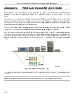
Page 107: ... End of BMC boot reset process Normal system operation Off Solid Green Indicates BMC Linux has booted and manageability functionality is up and running Fault Status LEDs operate as per usual 10 4 Post Code Diagnostic LEDs A bank of eight POST code diagnostic LEDs are located on the back edge of the server next to the stacked USB connectors During the system boot process the BIOS executes a number ...

Page 108: ...t the intended thermal requirements of these components It is the responsibility of the system integrator who chooses not to use Intel developed server building blocks to consult vendor datasheets and operating parameters to determine the amount of airflow required for their specific application and environmental conditions Intel Corporation cannot be held responsible if components fail or the ser...

Page 109: ...determine the amount of airflow required for their specific application and environmental conditions Intel Corporation cannot be held responsible if components fail or the server board does not operate correctly when used outside any of their published operating or non operating limits 11 2 MTBF The following is the calculated Mean Time Between Failures MTBF 40 degree C ambient air These values ar...

Page 110: ... as used in an Intel designed 4U server chassis P4000XXSFDR The intent of this section is to provide customers with a guide to assist in defining and or selecting a power supply for custom server platform designs that utilize the server boards detailed in this document Figure 26 Power Distribution Block Diagram 12 1 DC Output Specification 12 1 1 Output Power Currents The following table defines t...

Page 111: ...erating at steady state and dynamic loading conditions These limits include the peak peak ripple noise These shall be measured at the output connectors Table 55 Voltage Regulation Limits PARAMETER TOLERANCE MIN NOM MAX UNITS 12V 5 5 11 40 12 00 12 60 Vrms 12V stby 5 5 11 40 12 00 12 60 Vrms 12 1 4 Dynamic Loading The output voltages shall remain within limits specified for the step loading and cap...

Page 112: ...f Bode plots Closed loop stability must be ensured at the maximum and minimum loads as applicable 12 1 8 Residual Voltage Immunity in Standby Mode The power supply should be immune to any residual voltage placed on its outputs Typically a leakage voltage through the system from standby output up to 500mV There shall be no additional heat generated nor stressing of any internal components with this...

Page 113: ... the load sharing or output voltages of the other supplies still operating The supplies must be able to load share in parallel and operate in a hot swap redundant 1 1 configurations The 12VSBoutput is not required to actively share current between power supplies passive sharing The 12VSBoutput of the power supplies are connected together in the system so that a failure or hot swap of a redundant p...

Page 114: ...elay Delay from AC being applied to all output voltages being within regulation 3000 ms Tvout_holdup Time 12V output voltage stays within regulation after loss of AC at 70 load 13 ms Tpwok_holdu p Delay from loss of AC to de assertion of PWOK 12 ms Tpson_on_del ay Delay from PSON active to output voltages within regulation limits 5 400 ms T pson_pwok Delay from PSON deactivate to PWOK being de ass...

Page 115: ... 28 Turn On Off Timing Power Supply Signals AC Input Vout PWOK 12Vsb PSON Tsb_on_delay TAC_on_delay Tpwok_on Tvout_holdup Tpwok_holdup Tpson_on_delay Tsb_on_delay Tpwok_on Tpwok_off Tpwok_off Tpson_pwok Tpwok_low Tsb_vout AC turn on off cycle PSON turn on off cycle T5Vsb_holdup ...

Page 116: ...ported Clear CMOS with the AC power cord plugged in Removing AC power before performing the CMOS Clear operation causes the system to automatically power up and immediately power down after the CMOS Clear procedure is followed and AC power is re applied If this happens remove the AC power cord wait 30 seconds and then re connect the AC power cord Power up the system and proceed to the F2 BIOS Setu...

Page 117: ...ical Event triggers are supported event generating offsets for discrete type sensors The offsets can be found in the Generic Event Reading Type Code or Sensor Type Code tables in the Intelligent Platform Management Interface Specification Second Generation v2 0 depending on whether the sensor event reading type is generic or a sensor specific response Assertion De assertion Assertion and de assert...

Page 118: ...rovides the count of hysteresis for the sensor which can be 1 or 2 positive or negative hysteresis Criticality Criticality is a classification of the severity and nature of the condition It also controls the behavior of the front panel status LED Standby Some sensors operate on standby power These sensors may be accessed and or generate events when the main system power is off but AC power is pres...

Page 119: ...undancy1 Pwr Unit Redund 02h Chassis specific Power Unit 09h Generic 0Bh 00 Fully Redundant OK As Trig Offse t M X 01 Redundancy lost Degraded 02 Redundancy degraded Degraded 03 Non redundant sufficient resources Transition from full redundant state Degraded 04 Non redundant sufficient resources Transition from insufficient state Degraded 05 Non redundant insufficient resources Fatal 06 Redundant ...

Page 120: ...K As Trig Offse t A QPI Correctable Event QPI Corr Sensor 06h All Critical Event 13h 72h QPI Uncorrectable Event QPI Fatl Sensor 07h All Critical Event 13h 73h SMI Timeout SMI Timeout 06h All SMI Timeou t F3h Digital Discrete 03h 01 State asserted Fatal As and De Trig Offse t A System Event Log System Event Log 07h All Event Loggin g Disable d 10h Sensor Specific 6Fh 02 Log area reset cleared OK A...

Page 121: ...resources Transition from redundant Degraded 04 Non redundant Sufficient resources Transition from insufficient Degraded 05 Non redundant insufficient resources Non Fatal 06 Non Redundant degraded from fully redundant Degraded 07 Redundant degraded from non redundant Degraded SSB Thermal Trip SSB Therm Trip 0Dh All Tempe rature 01h Digital Discrete 03h 01 State Asserted Fatal As and De Trig Offse ...

Page 122: ...ture 5 Platform Specific 14h Platform specific Tempe rature 01h Threshol d 01h u l c nc nc Degraded c Non fatal As and De Analog R T A X Baseboard Temperature 6 Platform Specific 15h Platform specific Tempe rature 01h Threshol d 01h u l c nc nc Degraded c Non fatal As and De Analog R T A X IO Module2 Temperature I O Mod2 Temp 16h Platform specific Tempe rature 01h Threshol d 01h u l c nc nc Degrad...

Page 123: ...X Baseboard Temperature 2 Platform Specific 23h Platform specific Tempe rature 01h Threshol d 01h u l c nc nc Degraded c Non fatal As and De Analog R T A X Baseboard Temperature 3 Platform Specific 24h Platform specific Tempe rature 01h Threshol d 01h u l c nc nc Degraded c Non fatal As and De Analog R T A X Baseboard Temperature 4 Platform Specific 25h Platform specific Tempe rature 01h Threshol ...

Page 124: ...I Riser 2 Temp 2Ch Platform specific Tempe rature 01h Threshol d 01h u l c nc nc Degraded c Non fatal As and De Analog R T A X SAS Module Temperature SAS Mod Temp 2Dh Platform specific Tempe rature 01h Threshol d 01h u l c nc nc Degraded c Non fatal As and De Analog R T A X Exit Air Temperature Exit Air Temp 2Eh Chassis and Platform Specific Tempe rature 01h Threshol d 01h This sensor does not gen...

Page 125: ...2 AC Power Input PS2 Power In 55h Chassis specific Other Units 0Bh Threshol d 01h u c nc nc Degraded c Non fatal As and De Analog R T A X Power Supply 1 12V of Maximum Current Output PS1 Curr Out 58h Chassis specific Current 03h Threshol d 01h u c nc nc Degraded c Non fatal As and De Analog R T A X Power Supply 2 12V of Maximum Current Output PS2 Curr Out 59h Chassis specific Current 03h Threshol ...

Page 126: ...Specific 6Fh 01 Thermal trip FIVR Fatal As and De Trig Offse t M X 07 Presence OK Processor 3 Status P3 Status 72h Platform specific Proces sor 07h Sensor Specific 6Fh 01 Thermal trip Fatal As and De Trig Offse t M X 07 Presence OK Processor 4 Status P4 Status 73h Platform specific Proces sor 07h Sensor Specific 6Fh 01 Thermal trip Fatal As and De Trig Offse t M X 07 Presence OK Processor 1 Therma...

Page 127: ...1h u c nc nc Degraded c Non fatal As and De Analog Trig Offse t A Processor ERR2 Timeout CPU ERR2 7Ch All Proces sor 07h Digital Discrete 03h 01 State Asserted Fatal As and De Trig Offse t A Catastrophic Error CATERR 80h All Proces sor 07h Digital Discrete 03h 01 State Asserted Fatal As and De Trig Offse t M MTM Level Change MTM Lvl Change 81h All Mgmt Health 28h Digital Discrete 03h 01 State Asse...

Page 128: ...e t A Power Supply 1 Fan Fail 13 PS1 Fan Fail 1 A0h Chassis specific Fan 04h Generic digital discrete 03h 01 State Asserted Non fatal As and De Trig Offse t M X Power Supply 1 Fan Fail 23 PS1 Fan Fail 2 A1h Chassis specific Fan 04h Generic digital discrete 03h 01 State Asserted Non fatal As and De Trig Offse t M X PHI 1 Status GPGPU1 Status A2h Platform Specific Status C0h OEM Defined 70h PHI 2 St...

Page 129: ...c Non fatal As and De Analog R T A Processor 1 DIMM Aggregate Thermal Margin 2 P1 DIMM Thrm Mrgn2 B1h All Tempe rature 01h Threshol d 01h u c nc nc Degraded c Non fatal As and De Analog R T A Processor 2 DIMM Aggregate Thermal Margin 1 P2 DIMM Thrm Mrgn1 B2h All Tempe rature 01h Threshol d 01h u c nc nc Degraded c Non fatal As and De Analog R T A Processor 2 DIMM Aggregate Thermal Margin 2 P2 DIMM...

Page 130: ... B8h Multi Node Specific Power Unit 09h Generic digital discrete 03h 01 State Asserted Non fatal As and De Trig Offse t A Fan Tachometer Sensors Chassis specific sensor names BAh BFh Chassis and Platform Specific Fan 04h Threshol d 01h l c nc nc Degraded c Non fatal2 As and De Analog R T M Processor 1 DIMM Thermal Trip P1 Mem Thrm Trip C0h All Memor y 0Ch Sensor Specific 6Fh 0A Critical overtemper...

Page 131: ...ecific Tempe rature 01h Threshol d 01h Global Aggregate Temperature Margin 1 Agg Therm Mrgn 1 C8h Platform Specific Tempe rature 01h Threshol d 01h Analog R T A Global Aggregate Temperature Margin 2 Agg Therm Mrgn 2 C9h Platform Specific Tempe rature 01h Threshol d 01h Analog R T A Global Aggregate Temperature Margin 3 Agg Therm Mrgn 3 CAh Platform Specific Tempe rature 01h Threshol d 01h Analog R...

Page 132: ...l d 01h u l c nc nc Degraded c Non fatal As and De Analog R T A X Baseboard Temperature 6 MEM EFVRD Temp D6h Platform specific Tempe rature 01h Threshol d 01h u l c nc nc Degraded c Non fatal As and De Analog R T A X Voltage Fault Voltage Fault D1h All Voltage 02h Discrete 03h 01 Asserted Degraded A Baseboard CMOS Battery BB 3 3V Vbat DEh All Voltage 02h Threshol d 01h l c nc nc Degraded c Non fat...

Page 133: ... supplies are operational if the system is loaded beyond the capacity of a single power supply 2 This is only applicable when the system doesn t support redundant fans When fan redundancy is supported then the contribution to system state is driven by the fan redundancy sensor not individual sensors On a system with fan redundancy the individual sensor severities will read the same as the fan redu...

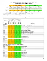
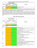
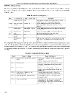
Page 134: ...ver board During a POST system hang the displayed post code can be used to identify the last POST routine that was run prior to the error occurring helping to isolate the possible cause of the hang condition Each POST code is represented by eight LEDs four Green and four Amber The POST codes are divided into two nibbles an upper nibble and a lower nibble The upper nibble bits are represented by Am...

Page 135: ...RAM initialization begin 04h 0 0 0 0 0 1 0 0 Pei Cache When Disabled 05h 0 0 0 0 0 1 0 1 SEC Core At Power On Begin 06h 0 0 0 0 0 1 1 0 Early CPU initialization during Sec Phase 07h 0 0 0 0 0 1 1 1 Early SB initialization during Sec Phase 08h 0 0 0 0 1 0 0 0 Early NB initialization during Sec Phase 09h 0 0 0 0 1 0 0 1 End Of Sec Phase 0Eh 0 0 0 0 1 1 1 0 Microcode Not Found 0Fh 0 0 0 0 1 1 1 1 Mic...

Page 136: ...PCI Bus assign resource 87h 1 0 0 0 0 1 1 1 DXE CON_OUT connect 88h 1 0 0 0 1 0 0 0 DXE CON_IN connect 89h 1 0 0 0 1 0 0 1 DXE SIO Init 8A 1 0 0 0 1 0 1 0 DXE USB start 8B 1 0 0 0 1 0 1 1 DXE USB reset 8C 1 0 0 0 1 1 0 0 DXE USB detect 8D 1 0 0 0 1 1 0 1 DXE USB enable 90h 1 0 0 0 0 0 0 0 DXE IDE begin 91h 1 0 0 1 0 0 0 1 DXE IDE reset 92h 1 0 0 1 0 0 1 0 DXE IDE detect 93h 1 0 0 1 0 0 1 1 DXE IDE...

Page 137: ...iagnostic Codes There are two types of POST Diagnostic Codes displayed by the MRC during memory initialization Progress Codes and Fatal Error Codes The MRC Progress Codes are displays to the Diagnostic LEDs that show the execution point in the MRC operational path at each step Table 63 MRC Progress Codes Checkpoint Diagnostic LED Decoder Description 1 LED On 0 LED Off Upper Nibble Lower Nibble MSB...

Page 138: ...gnostic LEDs Table 64 POST Progress LED Codes Checkpoint Diagnostic LED Decoder Description 1 LED On 0 LED Off Upper Nibble Lower Nibble MSB LSB 8h 4h 2h 1h 8h 4h 2h 1h LED 7 6 5 4 3 2 1 0 MRC Fatal Error Codes E8h 1 1 1 0 1 0 0 0 No usable memory error 01h No memory was detected from the SPD read or invalid config that causes no operable memory 02h Memory DIMMs on all channels of all sockets are ...

Page 139: ...D Off Upper Nibble Lower Nibble MSB LSB 8h 4h 2h 1h 8h 4h 2h 1h LED 7 6 5 4 3 2 1 0 02h Violation of DIMM population rules 03h The 3rd DIMM slot cannot be populated when QR DIMMs are installed 04h UDIMMs are not supported in the 3rd DIMM slot 05h Unsupported DIMM Voltage EFh 1 1 1 0 1 1 1 1 Indicates a CLTT table structure error ...

Page 140: ... in the BIOS setup determines whether the system pauses to the Error Manager for this type of error so the user can take immediate corrective action or the system continues booting Note For 0048 Password check failed the system halts and then after the next reset reboot will displays the error code on the Error Manager screen Fatal The system halts during post at a blank screen with the text Unrec...

Page 141: ...ization Major 8521 DIMM_A2 failed test initialization Major 8523 DIMM_B1 failed test initialization Major 8524 DIMM_B2 failed test initialization Major 8540 DIMM_A1 disabled Major 8541 DIMM_A2 disabled Major 8543 DIMM_B1 disabled Major 8544 DIMM_B2 disabled Major 8560 DIMM_A1 encountered a Serial Presence Detection SPD failure Major 8561 DIMM_A2 encountered a Serial Presence Detection SPD failure ...

Page 142: ...tegrated BMC may generate beep codes upon detection of failure conditions Beep codes are sounded each time the problem is discovered such as on each power up attempt but are not sounded continuously Codes that are common across all Intel server boards and systems that use same generation chipset are listed in the following table Each digit in the code is represented by a sequence of beeps whose co...

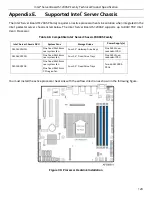
Page 143: ...rver Chassis P4000S Family Intel Server Chassis SKU System Fans Storage Drives Power Supply s P4304XXSHCN One fixed 92x38mm rear system fan Four 3 5 Hotswap Drive Bays One 365W non redundant PSU P4304XXSFCN One fixed 92x38mm rear system fan Four 3 5 Fixed Drive Trays One 365W non redundant PSU P4000XXSFDR One fixed 92x38mm rear system fan One fixed 92x32mm PCI region fan Four 3 5 Fixed Drive Trays...

Page 144: ... other CBCs Together they bridge the IPMB buses of multiple chassis CLI Command line interface CLTT Closed loop thermal throttling memory throttling mode CMOS In terms of this specification this describes the PC AT compatible region of battery backed 128 bytes of memory on the server board CSR Control and status register D cache Data cache Processor local cache dedicated for memory locations expli...

Page 145: ... equipment manufacturer OLTT Open loop thermal throttling memory throttling mode PCI Peripheral Component Interconnect PECI Platform Environmental Control Interface PEF Platform event filtering PET Platform event trap PIA Platform information area PLD Programmable logic device POST Power on self test PROM Programmable read only memory PSMI Power Supply Management Interface PWM Pulse Width Modulati...

Page 146: ...itive addressing for devices and bus arbitration SMI Server management interrupt SMI is the highest priority non maskable interrupt SMM Server management mode SMS Server management software SNMP Simple Network Management Protocol SOL Serial over LAN SPT Straight pass through SRAM Static random access memory UART Universal asynchronous receiver and transmitter UDP User Datagram Protocol UHCI Univer...

Page 147: ...2 0 2004 Intel Corporation Hewlett Packard Company NEC Corporation Dell Computer Corporation Platform Support for Serial over LAN SOL TMode and Terminal Mode External Architecture Specification Version 1 1 02 01 02 Intel Corporation Intel Remote Management Module User s Guide Intel Corporation Alert Standard Format ASF Specification Version 2 0 23 April 2003 2000 2003 Distributed Management Task F...

Reviews: