Intel® Server Board S1200SP Family Technical Product Specification
74
8.3.5
Chassis Intrusion Header
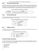
The Chassis Intrusion header is connected via a two-wire cable to a switch assembly that is mounted just under
the chassis cover on systems that support this feature. When the chassis cover is removed, the switch and thus
the electrical connection between the pins on this header become open allowing the BMC’s CHASIS_N pin to
be pulled LOW. The BMC’s CHASIS-N pin is used by FW to note the change in the chassis cover status.
Table 30. Chassis Intrusion Header Pin-out (J9B2)
Header State
Description
Pins 1 and 2 closed
BMC CHASIS_N is pulled HIGH. Chassis cover is closed.
Pins 1 and 2 open
BMC CHASIS_N is pulled LOW. Chassis cover is removed.
8.3.6
SATA SGPIO Header
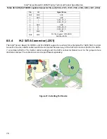
Two SATA SGPIO 5 pin headers are implemented on the Intel® Server Board S1200SPL and S1200SPO: one is
for Port0-3 (White) and the other is for Port4-7 (Black).
Table 31. SATA SGPIO Header Pin-out (J2K5, J2K6)
Pin
IO
Signal Name
1
I
SGPIO_CLOCK
2
I
SGPIO_LOAD
3
GND
GND
4
I
SGPIO_DATAOUT
5
O
SGPIO_DATAIN
8.3.7
IPMB Connector
An IPMB header is provided on the baseboard to support connectivity with other IPMI-compliant controllers
(e.g. 3
rd
party management PCIe* cards).
Table 32. IPMB Connector Pin-out (J1G2)
Pin
IO
Signal Name
1
IO
SMB_IPMB_5VSTBY_DATA
2
GND
GND
3
I
SMB_IPMB_5VSTBY_CLK
4
PWR
P5V_AUX
8.4
Front Panel Connector
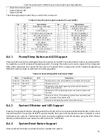
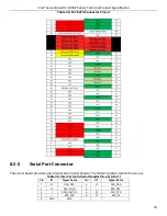
The server board provides a 24-pin front panel connector for use with Intel
®
and third-party chassis. The
connector consists of a 24-pin SSI compatible front panel connector. The 24-pin SSI front panel connector
provides various front panel features including:
•
Power/Sleep Button
•
System ID Button
•
NMI Button
•
NIC Activity LEDs
Summary of Contents for S1200SPL
Page 3: ......

