Intel® Server Board S1200SP Family Technical Product Specification
48
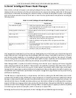
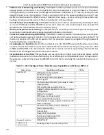
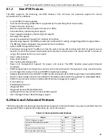
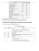
separate configurable fan control policy. A fan domain can have a set of temperature and fan sensors
associated with it. These are used to determine the current fan domain state.
A fan domain has three states: sleep, nominal, and boost. The sleep and boost states have fixed (but
configurable through OEM SDRs) fan speeds associated with them. The nominal state has a variable speed
determined by the fan domain policy. An OEM SDR record is used to configure the fan domain policy.
The fan domain state is controlled by several factors. They are listed below in order of precedence, high to low:
•
Boost
-
Associated fan is in a critical state or missing. The SDR describes which fan domains are boosted in
response to a fan failure or removal in each domain. If a fan is removed when the system is in ‘Fans-
off’ mode it will not be detected and there will not be any fan boost till system comes out of ‘Fans-off;
mode.
-
Any associated temperature sensor is in a critical state. The SDR describes which temperature-
threshold violations cause fan boost for each fan domain.
-
The BMC is in firmware update mode, or the operational firmware is corrupted.
-
If any of the above conditions apply, the fans are set to a fixed boost state speed.
•
Nominal
-
A fan domain’s nominal fan speed can be configured as static (fixed value) or controlled by the state
of one or more associated temperature sensors.
-
Hysteresis can be specified to minimize fan speed oscillation and to smooth fan speed transitions.
6.10.1
Thermal and Acoustic Management
This feature refers to enhanced fan management to keep the system optimally cooled while reducing the
amount of noise generated by the system fans. Aggressive acoustics standards might require a trade-off
between fan speed and system performance parameters that contribute to the cooling requirements, primarily
memory bandwidth. The BIOS, BMC, and SDRs work together to provide control over how this trade-off is
determined.
This capability requires the BMC to access temperature sensors on the individual memory DIMMs.
6.10.2
Thermal Sensor Input to Fan Speed Control
The BMC uses various IPMI sensors as input to the fan speed control. Some of the sensors are IPMI models of
actual physical sensors whereas some are virtual sensors whose values are derived from physical sensors
using calculations and/or tabular information.
The following IPMI thermal sensors are used as input to the fan speed control:
•
Front Panel Temperature Sensor
1
•
CPU Margin Sensors
2,4,5
•
DIMM Thermal Margin Sensors
2,4
•
Exit Air Temperature Sensor
1, 7, 9
•
PCH Temperature Sensor
3,5
•
Add-In Intel SAS Module Temperature Sensors
3, 5
•
PSU Thermal Sensor
3, 8
•
CPU VR Temperature Sensors
3, 6
•
DIMM VR Temperature Sensors
3, 6
•
BMC Temperature Sensor
3, 6
•
Global Aggregate Thermal Margin Sensors
7
•
Hot Swap Backplane Temperature Sensors
Summary of Contents for S1200SPL
Page 3: ......

