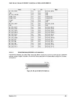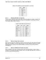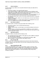
Intel® Server Chassis SC1400UP / Intel® Server Platform SR1425BK1-E
Revision 1.0
- 37 -
3.4.1
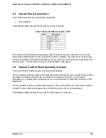
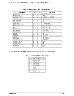
SATA Backplane Layout
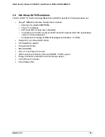
The SATA backplane is located on the backside of the hot-swap drive bays on the inside of the
chassis. Stand-offs on the chassis and a single thumb screw make for easy tool-less
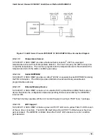
installation. The following diagram shows the layout of major components and connectors of the
board.
Figure 24. SATA Backplane Layout
Figure 25. SATA Backplane Layout
3.4.2
SATA Backplane Functional Architecture
This section provides a high-level description of the functionality distributed between the
architectural blocks of the SC1400UP 1U SATA HSBP. The figure below shows the functional
blocks of the SATA backplane.
SATA Drive
Connectors
Drive Status LEDs
Floppy Drive
Connector
not used
in SR1425BK1
Power Connector
IDE Connector
not
used in SR1425BK1
100-pin connector
not
used in SR1425BK1
Control Panel
Connector
not used in
SR1425BK1
SATA Connectors


