background image

122

Intel® Server Chassis SC5400 User’s Guide

Français

Le bloc d'alimentation de ce produit ne contient aucune pièce 

pouvant être réparée par l'utilisateur. Ce produit peut contenir plus 

d'un bloc d'alimentation. Veuillez contacter un technicien qualifié en 

cas de problème.

Ne pas essayer d'utiliser ni modifier le câble d'alimentation CA 

fourni, s'il ne correspond pas exactement au type requis. Le nombre 

de câbles d'alimentation CA fournis correspond au nombre de blocs 

d'alimentation du produit

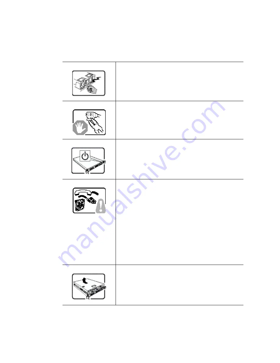
Notez que le commutateur CC de mise sous tension /hors tension 

du panneau avant n'éteint pas l'alimentation CA du système. Pour 

mettre le système hors tension, vous devez débrancher chaque 

câble d'alimentation de sa prise.

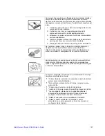
CONSIGNES DE SÉCURITÉ -Lorsque vous ouvrez le boîtier pour 

accéder à l'intérieur du système, suivez les consignes suivantes:

1. Mettez hors tension tous les périphériques connectés au 

système.

2. Mettez le système hors tension en mettant l'interrupteur 

général en position OFF (bouton-poussoir).

3. Débranchez tous les cordons d'alimentation c.a. du système 

et des prises murales.

4. Identifiez et débranchez tous les câbles reliés aux 

connecteurs d'E-S ou aux accès derrière le système.

5. Pour prévenir les décharges électrostatiques lorsque vous 

touchez aux composants, portez une bande antistatique pour 

poignet et reliez-la à la masse du système (toute surface 

métallique non peinte du boîtier).

6. Ne faites pas fonctionner le système tandis que le boîtier est 

ouvert.

Une fois TOUTES les étapes précédentes accomplies, vous pouvez 

retirer les panneaux du système. Procédez comme suit:

1. Si un cadenas a été installé sur à l'arrière du système, 

déverrouillez-le et retirez-le.

2. Retirez toutes les vis des panneaux et mettez-les dans un 

endroit sûr.

3. Retirez les panneaux.


Summary of Contents for SC5400

Page 1: ...Intel Server Chassis SC5400 User s Guide A Guide for Technically Qualified Assemblers of Intel Identified Subassemblies Products Intel Order Number D38435 005...

Page 2: ...make changes to specifications and product descriptions at any time without notice Intel server boards contain a number of high density VLSI and power delivery components that need adequate airflow fo...

Page 3: ...der Intel Server Deployment Toolkit CD oder unter http support intel com support motherboards server sb cs 010770 htm Consignes de s curit Lisez attention toutes les consignes de s curit et les mises...

Page 4: ...ssis add or remove any components Hazardous conditions devices and cables Hazardous electrical conditions may be present on power telephone and communication cables Turn off the server and disconnect...

Page 5: ...iers If your jumpers do not have such a tab take care when using needle nosed pliers to remove or install a jumper grip the narrow sides of the jumper with the pliers never the wide sides Gripping the...

Page 6: ...vi Intel Server Chassis SC5400 User s Guide...

Page 7: ...oards server chassis SC5400 Manual Organization Chapter 1 provides a brief overview of the Intel Server Chassis SC5400 In this chapter you will find a list of the server chassis features photos of the...

Page 8: ...ct box Intel Server Chassis SC5400 Quick Start User s Guide in the chassis hardware box Six 32 6mm flat screws for installing drive component in the chassis hardware box Seven screws for mounting the...

Page 9: ...ormation about this product including BIOS settings and chipset information IIntel Server Chassis SC5400 Technical Product Specification If you just received this product and need to install it Intel...

Page 10: ...x Intel Server Chassis SC5400 User s Guide...

Page 11: ...swap Drive Bays 12 Floppy CD ROM DVD ROM Slimline Carriers 12 Intel Remote Management Module 13 Rack mounted Systems 13 Chapter 2 Hardware Installations and Upgrades 15 Before You Begin 15 Tools and S...

Page 12: ...d Installing PCI Add in Board s 45 Removing PCI Add in Board s 45 Installing PCI Add in Board s 47 Installing Additional Hot Swap Power Supply Module 51 Replacing a Hot Swap Power Supply 52 Replacing...

Page 13: ...tent of Limited Warranty 84 Warranty Limitations and Exclusions 84 Limitations of Liability 84 How to Obtain Warranty Service 85 Telephone Support 85 Returning a Defective Product 85 Appendix D Safety...

Page 14: ...l acc s au syst me 102 Avertissements sur le montage en rack 102 D charges lectrostatiques ESD 103 Autres risques 103 Informaci n de seguridad del servidor 105 Advertencias y precauciones sobre segur...

Page 15: ...pper Device Bay 29 Figure 21 Attaching Slides to a DVD or CD ROM Drive 29 Figure 22 Removing Six drive Fixed Drive Cage from Chassis 31 Figure 23 Unlocking and Opening Upper Door of Fixed Drive Cage 3...

Page 16: ...in Board 48 Figure 51 Installing Add in Board 49 Figure 52 Reinstalling PCI Add in Card Retainer 50 Figure 53 Removing Power Supply Filler Panel 51 Figure 54 Installing Additional Hot Swap Power Suppl...

Page 17: ...hassis Features LXi SKU 5 Table 5 Front Control Panel LED Descriptions 8 Table 6 670 W Power Supply Output Capability 63 Table 7 830 W Power Supply Output Capability 64 Table 8 Environmental Specifica...

Page 18: ...xviii Intel Server Chassis SC5400 User s Guide...

Page 19: ...briefly describes the main features of the Intel Server Chassis SC5400 This chapter provides a list of the server chassis features as well as diagrams showing the location of important components and...

Page 20: ...ulti mount 5 25 peripheral bays Control Panel dependent on option selected Front Control Panel Intel Local Control Panel optional LEDs and displays dependent on option selected With Front Control Pane...

Page 21: ...ipherals Three multi mount 5 25 inch peripheral bays Control Panel dependent on option selected Front Control Panel Intel Local Control Panel optional LEDs and displays dependent on option selected Wi...

Page 22: ...mount 5 25 inch peripheral bays Control Panel dependent on option selected Front Control Panel Intel Local Control Panel optional LEDs and displays dependent on option selected With Front Control Pan...

Page 23: ...ls Three multi mount 5 25 inch peripheral bays Control Panel dependent on option selected Front Control Panel Intel Local Control Panel optional LEDs and displays dependent on option selected With Fro...

Page 24: ...L G H K E D J I AF000511 A Fixed Power Supply G Hard Disk Drive Cage Release Mechanisms 2 B Rear Serial B Connector H Front Panel Controls C PCI Add in Card Panel I 5 25 inch Device Bays D Memory Air...

Page 25: ...le on the Front Control Panel The Intel Local Control Panel is optional Figure 3 Front Control Panel TP00701 A B C E F G H I D A ID Toggle Switch F NIC2 Activity LED green B Reset Button G ID LED blue...

Page 26: ...on during BMC reset Amber On Critical alarm critical power module failure critical fan failure voltage power supply voltage and thermal fault Blink Non critical failure redundant fan failure redundant...

Page 27: ...ontrol Panel requires the installation of the Intel Remote Management Module See your server board documentation to determine if this control panel is compatible with your server board Figure 4 Intel...

Page 28: ...epending on the server board installed See your server board documentation for port identification Figure 5 Server Chassis Back A Fixed Power Supply B I O Ports C PCI Add in Card Slots D PCI Card Latc...

Page 29: ...rdware for installing hard drives a floppy drive a CD ROM drive or a DVD ROM drive The drives must be purchased separately The following figure shows the available options A Slimline floppy drive DVD...

Page 30: ...oes not support all SAS SATA or SCSI hard drives See Additional Information and Software on page ix for an Internet link to a list of supported hardware Floppy CD ROM DVD ROM Slimline Carriers For ins...

Page 31: ...ard Rack mounted Systems Your Intel Server Chassis SC5400 can be mounted into a rack Intel provides a tool less rail kit and a cable management arm to mount this server chassis into a rack When instal...

Page 32: ...14 Intel Server Chassis SC5400 User s Guide...

Page 33: ...s For instructions on replacing components on the server board such as the processor and memory DIMMs see the instructions provided with the server board Tools and Supplies Needed Phillips cross head...

Page 34: ...non skid surface or a stop behind the chassis may be needed to prevent the chassis from sliding on your work surface 1 Observe the safety and ESD precautions at the beginning of this book See Safety I...

Page 35: ...Slide the chassis cover on the chassis 2 Latch the cover securely to the chassis 3 If the chassis will be re shipped secure the chassis cover to the chassis with the access cover screw see letter A i...

Page 36: ...es and the AC power cable 3 Remove the chassis cover For instructions see Removing the Chassis Cover on page 16 4 Release the two plastic tabs see letter A in the following figure on the left side of...

Page 37: ...embly see letter A in the following figure 2 Remove the filler panels that correspond to installed devices see letter B 3 Close the outer bezel door see letter C 4 Fit the right edge of the bezel asse...

Page 38: ...e processor and memory air ducts after installing your processor and heat sink Removing the Processor and Memory Air Ducts 1 Observe the safety and ESD precautions at the beginning of this book See Sa...

Page 39: ...the inner air baffle in place and proceed to step two Figure 12 Removing Inner Plastic Air Baffle from Processor Air Duct 2 Install the processor air duct Make sure the tabs on the processor air duct...

Page 40: ...tter D engage and the memory air duct latch see letter E snaps into place Figure 13 Installing the Processor and Memory Air Ducts Caution The processor air duct interlocks with the memory air duct in...

Page 41: ...instructions see Removing the Chassis Cover on page 16 4 Disconnect the appropriate fan power cable from the server board 5 Remove the 92 mm see letter A in the following figure or 120 mm see letter...

Page 42: ...gurations ship with fixed fans The hot swap fans from the Intel Server Chassis SC5300LX cannot be used in the Intel Server Chassis SC5400LX or SC5400LXi 1 Observe the safety and ESD precautions at the...

Page 43: ...swap fans from the Intel Server Chassis SC5300 LX cannot be used in the Intel Server Chassis SC5400LX or SC5400LXi 1 Observe the safety and ESD precautions at the beginning of this book 2 Remove the c...

Page 44: ...wer cable 3 Remove the chassis cover For instructions see Removing the Chassis Cover on page 16 4 Remove the front bezel if it is installed For instructions see Removing and Installing the Front Bezel...

Page 45: ...he Chassis Cover on page 17 10 Plug all peripheral devices and the AC power cable into the server 11 Power up the server Removing and Installing a DVD or CD ROM Drive Removing a DVD or CD ROM Drive 1...

Page 46: ...mple on the drive 7 If not replacing with another drive re attach pair of slides to an EMI shield and re insert EMI shield slide assembly into chassis for proper airflow Figure 19 Re inserting Empty E...

Page 47: ...d Installing the Front Bezel on page 18 5 Remove an EMI shield slide assembly from the upper device bay by pressing the two slide assembly latches inward see letter A in the following figure Remove th...

Page 48: ...the AC power cable 3 Remove the chassis cover For instructions see Removing the Chassis Cover on page 16 4 Remove the front bezel if it is installed For instructions see Removing and Installing the Fr...

Page 49: ...2 Removing Six drive Fixed Drive Cage from Chassis 8 Loosen the thumb screw see letter A in the following figure Open the upper door of the drive cage see letter B Figure 23 Unlocking and Opening Uppe...

Page 50: ...s SC5400 User s Guide 9 Open the lower door Figure 24 Opening Lower Door of Fixed Drive Cage 10 Remove the drive slide assembly from the drive cage Figure 25 Removing Drive Slide Assembly from Drive C...

Page 51: ...vice slides from hard drive If not replacing hard drive insert empty device slides into drive cage Figure 26 Inserting Empty Device Slides into Drive Cage 12 Close the lower door of drive cage Figure...

Page 52: ...d drive into chassis 16 If other hard drives remain in the drive cage reconnect power and data cables 17 Install the front bezel For instructions see Removing and Installing the Front Bezel on page 18...

Page 53: ...the blue plastic release mechanism upward to release the fixed drive cage see letter A in the following figure Pull the drive cage out about two inches see letter B so that it is partially exposed fr...

Page 54: ...osen the captive screw see letter A in the following figure Open the upper door see letter B Figure 31 Unlocking and Opening Upper Door of Fixed Drive Cage 7 Open the lower door Figure 32 Opening Lowe...

Page 55: ...ice slides to the hard drive This is a tool less operation Insert pins on device slides into mounting holes on hard drive Press firmly to secure device slides to hard drive Ensure that the metal tabs...

Page 56: ...connector end of the hard drive faces towards the rear of the drive cage Figure 35 Inserting Drive Slide Assembly into Drive Cage 11 Repeat above steps for installation of additional hard drives into...

Page 57: ...install fixed drive cage into chassis 16 Connect power and data cables to connectors on hard drive s 17 Install the front bezel For instructions see Removing and Installing the Front Bezel on page 18...

Page 58: ...e bay and upper device bay Power Cable Routing Guidelines P3 P4 and P5 power cables route to removable drives P6 P7 P8 P9 P10 and P11 power cables standard SAS SATA route as appropriate P12 and P13 po...

Page 59: ...supplied with the fixed drive bay kit Route SAS SATA data cables through the chassis openings located near the bottom of the drive cage Connect data cables to the respective fixed drive and to the app...

Page 60: ...wards to unlatch the drive carrier With the black lever open remove the drive carrier from the drive cage Figure 41 Releasing Drive Carrier from Hot Swap Cage 2 Remove the four screws securing the har...

Page 61: ...formerly attached to the hard drive Note Plastic air baffles are necessary in all empty drive carriers to ensure proper airflow within the chassis Figure 43 Installing Plastic Air Baffle in Drive Carr...

Page 62: ...t swap drive cage Slide the drive carrier out of the drive cage see letter C Figure 45 Removing Drive Carrier from Hot Swap Cage 3 Remove the four screws that secure the plastic air baffle to the driv...

Page 63: ...guide at the front of the chassis to release the card from the card guide 1 Observe the safety and ESD precautions at the beginning of this book 2 Power down the server and unplug all peripheral devic...

Page 64: ...Chassis SC5400 User s Guide Open the back panel PCI add in card retention device see letter B by pressing open from the inside of the chassis Figure 49 Preparing Chassis for Removal of PCI Add in Boar...

Page 65: ...Board s Caution You may want to install an operating system before installing any add in boards Do not overload the server board by installing add in boards that draw excessive current Add in boards...

Page 66: ...r C if it has not already been removed by pushing the shield out from the inside of the chassis Figure 50 Preparing Chassis for Addition of PCI Add in Board 6 Remove the PCI add in board from its prot...

Page 67: ...corners Firmly press the add in board into an expansion slot on the server board see letter A in the following figure Close the back panel PCI add in card retention device see letter B Figure 51 Insta...

Page 68: ...ainer 10 Attach cables if necessary 11 Install the front bezel For instructions see Removing and Installing the Front Bezel on page 18 12 Install the chassis cover For instructions see Installing the...

Page 69: ...s has a fixed power supply 1 Remove screws see letter A in the following figure Remove the power supply filler panel see letter B Figure 53 Removing Power Supply Filler Panel 2 Insert the power supply...

Page 70: ...present remove shipping screw securing defective hot swap power supply to chassis see letter A in the following figure Press on green latch see letter B while pulling on handle to remove power supply...

Page 71: ...hassis components and server board 5 Remove the eight screws securing the fixed power supply shield to the chassis see letter A in the following figure Remove the fixed power supply see letter B Figur...

Page 72: ...emove the chassis cover For instructions see Removing the Chassis Cover on page 16 4 Remove the memory and processor air ducts For instructions see Removing the Processor and Memory Air Ducts on page...

Page 73: ...center divider straight back see letter B to release tabs from chassis slots Then while holding the right edge of the center divider at a downward angle disengage tabs from chassis wall by pushing ce...

Page 74: ...ution board off of the standoffs see letter B and then remove it through the back of the power supply cage see letter C You may have to feed the power cables through the power supply cage while removi...

Page 75: ...y cage Push down on the power distribution board to securely attach it to the standoffs see letter B Tighten thumb screw see letter C Note Cables on back of power distribution board not shown to clari...

Page 76: ...cure to chassis with one screw see letter B Figure 62 Re installing Center Divider 13 Insert hot swap power supply ies into chassis Replace shipping screw s see letter A in the following figure if shi...

Page 77: ...ystem turn off the system by pressing the power button and unplug the AC power cord from the system or wall outlet 1 Observe the safety and ESD precautions at the beginning of this book 2 Power down t...

Page 78: ...er board for installation instructions Use the mounting screws bumpers and standoffs if necessary that came with your chassis to secure the server board to the chassis Make sure the server board is pr...

Page 79: ...bles that route toward the server board to the chassis Connecting Cables to Server Board 1 If your server has a hot swap power supply connect the cables that route toward the server board to the chass...

Page 80: ...62 Intel Server Chassis SC5400 User s Guide...

Page 81: ...for your configuration see Calculating Power Usage on page 65 Warning Do not exceed a combined power output of 170 Watts for the 5 V and 3 3 V outputs Exceeding a combined 170 Watts will overload the...

Page 82: ...m and may cause the power supplies to overheat and malfunction The expansion slots on the server board are rated for no more than 25 Watts for any one slot The average current usage per slot should no...

Page 83: ...vendor documents Worksheet Calculating DC Power Usage Table 9 Power Usage Worksheet Current maximum at voltage level Device 3 3 V 5 V 5 V 12 V 12 V 5 V Standby Baseboard Front Panel Board and Fans Pr...

Page 84: ...ower usage for the power subsystem Caution Do not exceed a combined power output of 170 Watts for the 5 V and 3 3 V outputs Exceeding a combined 170 Watts will overload the power subsystem and may cau...

Page 85: ...th a microprocessor from the same family or higher and operating at the same or higher speed as the microprocessor used on this server board The final configuration of your end system product may requ...

Page 86: ...ons requirements are to Class A Table 11 Product Regulatory Compliance Markings Compliance Regional Description Compliance Reference Compliance Reference Marking Example Australia New Zealand AS NZS 3...

Page 87: ...3 3 Voltage Flicker CE Declaration of Conformity Germany GS Certification EN60950 International CB Certification IEC60950 CISPR 22 CISPR 24 None Required Japan VCCI Certification Korea RRL Certificat...

Page 88: ...ation GOST R 29216 91 Emissions GOST R 50628 95 Immunity Ukraine Ukraine Certification None Required Taiwan BSMI CNS13438 R33025 Table 11 Product Regulatory Compliance Markings Compliance Regional Des...

Page 89: ...ot occur in a particular installation If this equipment does cause harmful interference to radio or television reception which can be determined by turning the equipment off and on the user is encoura...

Page 90: ...e Canadian Department of Communications Europe CE Declaration of Conformity This product has been tested in accordance to and complies with the Low Voltage Directive 73 23 EEC and EMC Directive 89 336...

Page 91: ...ertification Recipient Intel Corporation 4 Date of Manufacturer Refer to date code on product 5 Manufacturer Nation Intel Corporation Refer to country of origin marked on product CNCA CCC China The CC...

Page 92: ...asures on the Control of Pollution Caused by Electronic Information Products EIP 39 Referred to as China RoHS Mark requires to be applied to retail products only Mark used is the Environmental Friendl...

Page 93: ...fication All materials parts and subassemblies must not contain restricted materials as defined in Intel s Environmental Product Content Specification of Suppliers and Outsourced Manufacturers http su...

Page 94: ...d Multiple Power Cords Multiple Power Cords Warnings Applied to product if more than one power cord is used English This unit has more than one power supply cord To reduce the risk of electrical shock...

Page 95: ...have a printed wiring board flammability rating of minimum UL94V 1 Add in boards containing external power connectors and or lithium batteries must be UL recognized or UL listed Any add in board cont...

Page 96: ...r s Guide End of Life Product Recycling Product recycling and end of life take back systems and requirements vary by country Contact the retailer or distributor of this product for information about p...

Page 97: ...s is considered the disconnect device to the main AC power The socket outlet that the system plugs into shall be installed near the equipment and shall be easily accessible SAFETY STEPS Whenever you r...

Page 98: ...r and heat sink may be hot if the system has been running Also there may be sharp pins and edges on some board and chassis parts Contact should be made with care Consider wearing protective gloves Dan...

Page 99: ...echselstrom Netzkabel aus der Steckdose bzw dem Netzger t um den Stromanschlu des Systems zu unterbrechen SICHERHEISMASSNAHMEN Immer wenn Sie die Geh useabdeckung abnehmen um an das Systeminnere zu ge...

Page 100: ...Abdeckung wieder anzubringen 1 Vergewissern Sie sich da Sie keine Werkzeuge oder Teile im Innern des Systems zur ckgelassen haben 2 berpr fen Sie alle Kabel Zusatzkarten und andere Komponenten auf or...

Page 101: ...sein keine starken von elektrischen Ger ten erzeugten elektromagnetischen Felder aufweisen in Regionen in denen elektrische St rme auftreten mit einem berspannungsschutzger t verbunden sein w hrend ei...

Page 102: ...l int rieur du syst me suivez les consignes suivantes 1 Mettez hors tension tous les p riph riques connect s au syst me 2 Mettez le syst me hors tension en mettant l interrupteur g n ral en position O...

Page 103: ...broches aigu s des cartes et aux bords tranchants du capot Nous vous recommandons l usage de gants de protection Danger d explosion si la batterie n est pas remont e correctement Remplacer uniquement...

Page 104: ...tapa del chasis para acceder al interior del sistema siga las siguientes instrucciones 1 Apague todos los dispositivos perif ricos conectados al sistema 2 Apague el sistema presionando el interruptor...

Page 105: ...r en cuenta que en el chasis o en el tablero puede haber piezas cortantes o punzantes Por ello se recomienda precauci n y el uso de guantes protectores Existe peligro de explosi n si la pila no se cam...

Page 106: ...all interno del sistema seguire i seguenti passi 1 Spegnere tutti i dispositivi periferici collegati al sistema 2 Spegnere il sistema usando il pulsante spento acceso dell interruttore del sistema 3...

Page 107: ...Fare attenzione alla presenza di piedini appuntiti e parti taglienti sulle schede e sul telaio consigliabile l uso di guanti di protezione Esiste il pericolo di un esplosione se la pila non viene sos...

Page 108: ...128 Intel Server Chassis SC5400 User s Guide...

Page 109: ...h existing product certifications and approvals Use only the described regulated components specified in this guide Use of other products components will void the UL Listing and other regulatory appro...

Page 110: ...ces of vibration or physical shock Isolated from strong electromagnetic fields produced by electrical devices In regions that are susceptible to electrical storms we recommend you plug your system int...

Page 111: ...inside the power supply Return to manufacturer for servicing When replacing a hot plug power supply unplug the power cord to the power supply being replaced before removing it from the server To avoid...

Page 112: ...n running any installed processor s and heat sink s may be hot Unless you are adding or removing a hot plug component allow the system to cool before opening the covers To avoid the possibility of com...

Page 113: ...old boards only by their edges After removing a board from its protective wrapper or from the server place the board component side up on a grounded static free surface Use a conductive foam pad if av...

Page 114: ...m parts To install the covers Check first to make sure you have not left loose tools or parts inside the system Check that cables add in boards and other components are properly installed Attach the c...

Page 115: ...ssenen Komponenten die im vorliegenden Handbuch angegeben werden Die Verwendung anderer Produkte oder Komponenten f hrt zum Erl schen der UL Zulassung und anderer Genehmigungen f r das Produkt Dadurch...

Page 116: ...mt von starken elektromagnetischen Feldern die durch elektrische Ger te erzeugt werden In gewittergef hrdeten Gebieten sollten Sie das System an einen berspannungsschutz anschlie en und bei einem Gewi...

Page 117: ...ie keine nderungen am Netzkabel vor und verwenden Sie kein Kabel das nicht genau dem geforderten Typ entspricht Jedes Netzteil im System mu ber ein eigenes Netzkabel angeschlossen werden Einige Netzte...

Page 118: ...chalten Sie alle am Produkt angeschlossenen Peripherieger te aus Schalten Sie das System mit dem Netzschalter aus Trennen Sie das Ger t von der Stromquelle indem Sie alle Netzkabel vom System bzw aus...

Page 119: ...tromzufuhr zur gesamten Einheit steuert und nicht nur zu den Servern Zur Vermeidung von Stromschlaggefahr m ssen das Rack selbst und alle darin eingebauten Ger te ordnungsgem geerdet sein Elektrostati...

Page 120: ...nur mit angebrachten Geh useabdeckungen betrieben werden Die Inbetriebnahme des Systems ohne Abdeckung kann zur Besch digung von Systemkomponenten f hren So bringen Sie die Abdeckung wieder an Vergew...

Page 121: ...uits composants annulera la liste UL et les autres approbations r glementaires du produit et le produit peut ne pas tre conforme aux autres lois et r glementations locales applicables au produit S cur...

Page 122: ...eurs l cart des sources de vibration ou des chocs physiques Isol des champs lectromagn tiques importants produits par des appareils lectriques Dans les r gions sujettes aux orages magn tiques nous vou...

Page 123: ...ue vous remplacez un bloc d alimentation chaud d branchez le cordon du bloc d alimentation en cours de remplacement avant de le retirer du serveur Pour viter tout risque d lectrocution mettez le syst...

Page 124: ...imentation en cours de remplacement avant de retirer le bloc du serveur Attention Si le serveur a t utilis les processeurs et dissipateurs de chaleur install s peuvent tre chauds moins que vous n ajou...

Page 125: ...api de mousse conducteru mais pas l emballage de la carte Veillez ce que la carte ne glisse sur aucune surface Autres risques Remplacement de la pile Attention Il existe un risque d explosion si la pi...

Page 126: ...s laser Attention Pour viter tout risque d exposition aux rayonnements et ou de dommage personnel N ouvrez pas l enceinte d un p riph rique laser Les p riph riques laser ne sont pas r parables par l u...

Page 127: ...se especifican en esta gu a El uso de otros productos o componentes anular la homologaci n UL y otras certificaciones oficiales del producto pudiendo dejar de ser compatible con las normativas locales...

Page 128: ...radiadores Alejada de fuentes de vibraci n o de golpes f sicos Aislada de campos electromagn ticos producidos por dispositivos el ctricos En zonas propensas a tormentas el ctricas se recomienda que c...

Page 129: ...ensi n corriente y energ a peligrosos Devu lvala al fabricante para repararla Al reemplazar una fuente de alimentaci n de conexi n en funcionamiento desenchufe el cable de alimentaci n de la fuente de...

Page 130: ...gar o reemplazar cualquier componente que no es de conexi n en funcionamiento Al reemplazar una fuente de alimentaci n de conexi n en funcionamiento desenchufe el cable de alimentaci n de la fuente de...

Page 131: ...las descargas electrost ticas Suj telas s lo por los bordes Una vez extra da la tarjeta de su envoltorio de protecci n o del servidor col quela con el lado de los componentes hacia arriba sobre una s...

Page 132: ...nes del producto Perif ricos o dispositivos l ser Precauci n Para evitar el riesgo de la exposici n a radiaciones o de da os personales No abra la caja de ning n perif rico o dispositivo l ser Los per...

Page 133: ...Intel Server Chassis SC5400 User s Guide 111 Intel Intel Intel Web...

Page 134: ...112 Intel Server Chassis SC5400 User s Guide ITE ITE 5V...

Page 135: ...Intel Server Chassis SC5400 User s Guide 113...

Page 136: ...114 Intel Server Chassis SC5400 User s Guide ESD ESD ESD ESD ESD...

Page 137: ...Intel Server Chassis SC5400 User s Guide 115...

Page 138: ...116 Intel Server Chassis SC5400 User s Guide...

Page 139: ...r reasons covered by this Limited Warranty Intel at its option will REPAIR the Product by means of hardware and or software OR REPLACE the Product with another Product OR REFUND the then current value...

Page 140: ...arranty lasts so this limitation may not apply to you Limitations of Liability Intel s responsibility under this or any other warranty implied or expressed is limited to repair replacement or refund a...

Page 141: ...instructions http support intel com support motherboards draform htm In Europe and in Asia Contact your original authorized distributor for warranty service Any replacement Product is warranted under...

Page 142: ...86 Intel Server Chassis SC5400 User s Guide...

Page 143: ...t at any time without notice Before calling fill out an Intel Server Issue Report Form available from the Web at http support intel com support motherboards server SC5400 For the fastest service submi...

Page 144: ...6 9796 via Philippines New Zealand 0800 444 365 Pakistan 632 63684 15 IDD via Philippines Philippines 1 800 1 651 0117 Singapore 65 6213 1311 Taiwan 2 2545 1640 Thailand 1 800 631 0003 Vietnam 632 636...

Page 145: ...Pacifictel Contact AT T USA at 1 800 225 528 Once connected dial 800 843 4481 Guatemala Contact AT T USA at 99 99 190 Once connected dial 800 843 4481 Mexico Contact AT T USA at 001 800 462 628 4240...

Page 146: ...70 Intel Server Chassis SC5400 User s Guide...

Reviews: