Intel® Server Board SE7520AF2 TPS
Connectors, Headers and Jumpers
Revision 1.2
233
Intel order number C77866-003
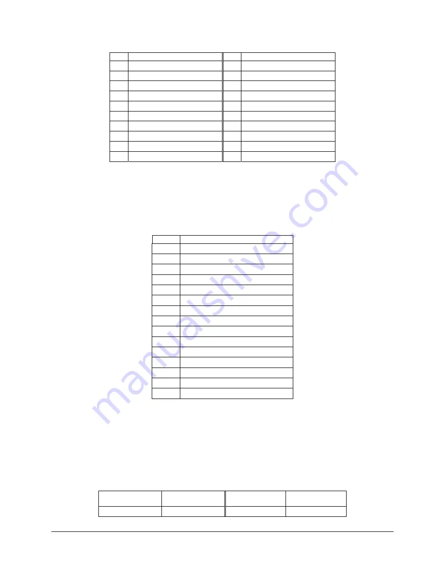
Pin
Signal Name
Pin
Signal Name
15
Reset Switch
16
I2C SDA
17
GND (Reset Switch)
18
I2C SCL
19
ACPI Sleep Switch
20
Chassis Intrusion
21
GND (ACPI Sleep Switch)
22
NIC2 Activity LED Anode
23
NMI to CPU Switch
24
NIC2 Activity LED Cathode
25 KEY
26 Key
27
ID LED Anode
28
System Ready Anode
29
ID LED Cathode
30
System Ready Cathode
31
ID Switch
32
HDD Fault Anode
33
GND (ID Switch)
34
HDD Fault Cathode
8.9 VGA
Connector
The following table details the pin-out of the VGA connector.
Table 126. VGA Connector Pin-out (J8A1)
Pin
Signal Name
1
Red (analog color signal R)
2
Green (analog color signal G)
3
Blue (analog color signal B)
4 No
connection
5 GND
6 GND
7 GND
8 GND
9 No
connection
10 GND
11 No
connection
12 DDCDAT
13
HSYNC (horizontal sync)
14
VSYNC (vertical sync)
15 DDCCLK
8.10 SCSI Connector
The Intel® Server Board SE7520AF2 provides two internal wide SCSI connectors (Channel A =
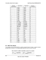
J1H1, Channel B = J1F1). The following table details the pin-out of the SCSI connectors.
Table 127. 68-pin SCSI Connector Pin-out (J1H1, J1F1)
Connector
Contact Number
Signal Name
Signal Name
Connector
Contact Number
1 +DB(12)
-DB(12)
35


