background image

Platform Installations and Upgrades 

Intel

®

 Carrier Grade Server TIGI2U User Guide 


37 

Removing and Installing the Front Bezel 

The front bezel needs to be removed only to install or remove hot-swap hard drives or the 

CDROM drive. 

Removing the Front Bezel  

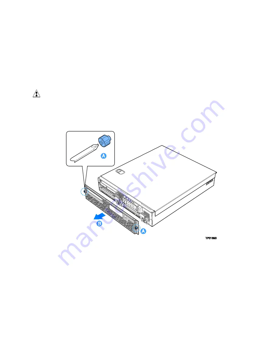
1.  Loosen the captive screws at the left and right edges of the front bezel (one screw at 

the right and one screw at the left; see letter “A”).  

  NOTE 

Hold the bezel in place while you loosen the screws. After both 

screws are loosened, the bezel will drop from the chassis.   


2.  Remove the front bezel from the chassis (see letter “B”). 


Figure 12.  Removing the Front Bezel 


Summary of Contents for TIGI2U - Carrier Grade Server

Page 1: ...Intel Carrier Grade Server TIGI2U User Guide A Guide for Technically Qualified Assemblers of Intel Identified Subassemblies Products Order Number D15006 004 ...

Page 2: ...r Intel may make changes to specifications and product descriptions at any time without notice Intel server boards contain a number of high density VLSI and power delivery components that need adequate airflow for cooling Intel s own chassis are designed and tested to meet the intended thermal requirements of these components when the fully integrated system is used together It is the responsibili...

Page 3: ...t diagrams to help you identify components and their locations Chapter 2 provides instructions on adding and replacing components Use this chapter for step by step instructions and diagrams for installing or replacing components such as the memory processor front panel board the battery and other components Chapter 3 provides instructions on using the utilities that are shipped with the board or t...

Page 4: ...ed Module See the Intel Carrier Grade Server TIGI2U Hardware Reference Guide for initial installation instructions Product Accessories You may need or want to purchase one or more of the following accessory items for your server One Intel Xeon Processor 3 2 GHz with an 800 MHz system bus One processor heat sink DDR2 400 memory DIMMs Hard disk drives HDDs PCI Peripheral Component Interconnect add i...

Page 5: ... as a reference before working with your server product pay close attention to the safety instructions You must adhere to the assembly instructions in this guide to ensure and maintain compliance with existing product certifications and approvals Use only the described regulated components specified in this guide Use of other products components will void the UL listing and other regulatory approv...

Page 6: ...t to prevent it from falling over when one or more servers are extended in front of the rack on slides You must also consider the weight of any other device installed in the rack A crush hazard exists should the rack tilt forward which could cause serious injury If AC power supplies are installed Mains AC power disconnect The AC power cord s is considered the mains disconnect for the server and mu...

Page 7: ...ontrolling power to the server The circuit breaker of a centralized DC power system may be used as a disconnect device when easily accessible and should be rated no more than 10 amps Grounding the server To avoid the potential for an electrical shock hazard you must reliably connect an earth grounding conductor to the server The earth grounding conductor must be a minimum 14AWG connected to the ea...

Page 8: ...cation by an agency acceptable in your region and for U S must be Listed and rated 125 of overall current rating of the server Connector server end The connectors that plug into the AC receptacle on the server must be an approved IEC International Electrotechnical Commission 320 sheet C13 type female connector Cord length and flexibility Cords must be less than 4 5 meters 14 76 feet long CAUTION T...

Page 9: ...m 重要安全指导 在执行任何指令之前 请阅读本文档中的所有注意事项及安全声明 参见 Resource CD 资源光盘 和 或 http support intel com support motherboards server sb CS 010770 htm 上的 Intel Server Boards and Server Chassis Safety Information Intel 服务器主板与服务器机箱安全信息 Consignes de sécurité Lisez attention toutes les consignes de sécurité et les mises en garde indiquées dans ce document avant de suivre toute instruction Consultez Intel Server Boards an...

Page 10: ...rades 33 Before You Begin 33 Tools and Supplies Needed 33 System References 33 Cable Routing Reference 33 Removing and Installing the Chassis Cover 35 Removing the Chassis Cover 35 Installing the Chassis Cover 36 Removing and Installing the Front Bezel 37 Removing the Front Bezel 37 Installing the Front Bezel 38 Removing and Installing the Processor Air Duct 39 Removing the Processor Air Duct 39 I...

Page 11: ...g the Power Interface Board 70 Replacing the Serial Alarms Cable 70 Removing the Serial Alarms Cable 71 Installing the Serial Alarms Cable 72 Replacing the Server Board 73 Removing the Server Board 73 Installing the Server Board 75 Replacing the Backup Battery 77 Installing or Replacing the Power Cord 79 Installing the Platform into a Rack 79 Equipment Rack Precautions 79 Server Utilities 82 Using...

Page 12: ... BIOS Error Messages 97 BIOS POST Beep Codes 98 Regulatory and Certification Information 100 Product Regulatory Compliance 100 Product Safety Compliance 100 Product EMC Compliance Class A Compliance 100 Certifications Registrations Declarations 101 Product Regulatory Compliance Markings 101 Electromagnetic Compatibility Notices 102 FCC USA 102 Industry Canada ICES 003 103 Europe CE Declaration of ...

Page 13: ...sembly into Chassis 48 Figure 25 Removing CD ROM DVD ROM Drive Assembly from Chassis 49 Figure 26 Install CD ROM Drive or DVD ROM Drive Assembly into Chassis 50 Figure 27 Removing Riser Assembly from Chassis 51 Figure 28 Installing Low Profile PCI Card into Riser 52 Figure 29 Installing Full Length PCI Card into Riser 53 Figure 30 Removing a Low Profile PCI Card 54 Figure 31 Removing a Full Height...

Page 14: ...erial Alarms Connector into Chassis 72 Figure 52 Installing the Serial Alarms Cable Threaded Standoffs 72 Figure 53 Removing the Server Board 74 Figure 54 Installing the Server Board 75 Figure 55 Securing SCSI Cable to Server Board Connector 76 Figure 56 Replacing the Battery 78 Figure 57 Password Recovery Jumper 85 Figure 58 CMOS Recovery Jumper 86 ...

Page 15: ... 17 Table 2 NIC LEDs 20 Table 3 Configuration Jumper J1H2 24 Table 4 LED Activity Definitions 25 Table 5 Keyboard Commands 83 Table 6 BIOS Error Messages 97 Table 7 POST Error Beep Codes 98 Table 8 Error Beep Codes Provided by Intel Management Modules 98 Table 9 Product Certification Markings 101 ...

Page 16: ... the main features of the Intel Carrier Grade Server TIGI2U This chapter provides a diagram of the product a list of the server features and diagrams showing the location of important components and connections on the server platform The Intel Carrier Grade Server TIGI2U is shown in the following diagram Figure 1 Intel Carrier Grade Server TIGI2U ...

Page 17: ...compliant with less than ten feet of external cable U320 high density 80 pin SCSI connector channel B Internal connections Two USB port headers each of which supports two USB 2 0 ports One DH10 Serial A header One Ultra320 80 pin SCSI connector Channel A One ATA 100 connector SSI compliant 34 pin high density 100 pin and alternate 50 pin control panel headers Intel Management Module 120 pin connec...

Page 18: ...ecification LAN Dual Intel 82546GB 10 100 1000 NICs Fans Two 80mm x 38mm fans Two 40mm x 28mm fans Server Management Diagnostics On board Platform Instrumentation using the National Semiconductor PC87431M mini Baseboard Management Controller mBMC Default Support for optional Intel Management Module Advanced Edition or Professional Edition Support for Intel Server Management 8 x Intel Light Guided ...

Page 19: ... Platform Components A Power Distribution Board F System Fans B Processor Air Duct G Front Panel I O Board C Power Supplies H SCSI Hard Disk Drive Carriers D PCI Riser Card Assembly I Peripheral Bay CD ROM or DVD ROM drive E Intel Server Board SE7520JR2 Figure 2 System Components ...

Page 20: ... Supply L USB 0 F PS 2 Mouse and Keyboard Connectors M Server Management Port G Rear Serial Port N SCSI Channel B Figure 3 Platform Back The NIC LEDs at the right and left of each NIC provide the following information Table 2 NIC LEDs NIC LED Color LED State Description NIC1 NIC2 Gigabit Left LED Off No network connection Solid Amber Network connection in place Blinking Amber Transmit receive acti...

Page 21: ...nce of a Major System Fault A major system fault is an error or event that is detected by the system that has discernable impact to system operation In this case the system can continue to operate but in a degraded fashion reduced performance or loss of non fatal feature reduction An example is the loss of one of two mirrored disks The front panel major alarm relay will be engaged E Minor amber Wh...

Page 22: ...Activity Fault LED green amber Indicates disk 0 SCSI hard drive activity when green or a disk 0 SCSI hard drive fault when amber Front of Server Platform N Optional CD ROM or DVD ROM Drive O Serial B via RJ45 P USB 2 Q Anti static Connection R Drive Carrier 0 S Drive Release Lever T Drive Carrier 1 U Drive Release Lever Figure 4 Front of Server Platform Server Platform Peripherals The platform pro...

Page 23: ...ull height riser slot L 24 pin SSI power connector D Low profile riser slot M 50 pin control panel connector E Back panel I O ports N Power supply signal cable F DIMM sockets O USB header 1 x 10 G Processor socket 1 P IDE power connector H Processor socket 2 Q SCSI channel A I 12V processor power R 120 pin connector for Intel Management Module Figure 6 Intel Server Platform TIGI2U Board Diagram ...

Page 24: ... not be jumpered for normal operation Recovery Boot line B in figure above 1 2 These pins should be jumpered for normal system operation 2 3 If these pins are jumpered the system will attempt to recover the BIOS by loading the BIOS code into the flash device from a floppy disk This jumper is typically used when the BIOS has become corrupted These pins should not be jumpered for normal operation CM...

Page 25: ...isk drives 1 and 2 IDE Bus from IDE Connector to blind mate connector One blind mate connector for interfacing to CDROM or floppy drive carrier assembly Connectors for interfacing to the power supply server baseboard drive carrier assemblies and hot plug disk drives 1 and 2 FPIO SCSI Subsystem Status LEDs The status LEDs give the user a visual indication of the drives condition There is a single L...

Page 26: ...ling or Removing a Hard Drive NOTE The Intel Carrier Grade Server TIGI2U does not support all SCSI hard drives For a list of validated hard drive manufacturers and hard drive types see http support intel com support motherboards server TIGI2U Drives can consume up to 17 watts of power each Drives must be specified to run at a maximum ambient temperature of 45 C Interconnect System SysCon Board The...

Page 27: ... of power at the following voltages DC Power Supply PARAMETER MIN RATED MAX Max Input Current DC Voltage 38 VDC 48VDC 60VDC 75VDC 20 5ADC AC Power Supply PARAMETER MIN RATED MAX Start up Vac Power Off Vac Max Input AC Current Max Rated Input AC Current Line Voltage 110 90Vrms 100 127 Vrms 140Vrms 85Vac 4Vac 75Vac 5Vac 10 0 Arms 1 3 8 9Arms 4 Line Voltage 220 180Vrms 200 240 Vrms 264Vrms 5 0 Arms 2...

Page 28: ...d exhausts through the rear of the chassis Each fan provides tachometer signal output to the server baseboard to indicate a fan failure The cooling subsystem contains a fan array consisting of two 80 x 38 mm fans and two 40 x 28 mm fans to cool the server board and other components A fan failure is indicated by one of the fault LEDs located on the front panel Hardware Requirements To avoid integra...

Page 29: ...et the following requirements Use only DDR2 400 ECC registered DDR DIMM modules Use only DIMMs that comply with the DDR specifications Use only DIMMs with DIMM organization of x72 ECC Use only 240pin DIMMs NOTE When using DDR2 400 DIMM technologies a maximum of four loads per memory channel is supported When all DIMMs used in the system match this technology a maximum of four DIMMs can be populate...

Page 30: ... DIMM in socket 3B takes over If the DIMM in socket 2B fails the DIMM in socket 3A takes over For memory on line sparing one DIMM per channel is used as the memory spare The spare DIMM is not available for use but is kept in reserve If a DIMM begins to fail the content of the failing DIMM is copied to the spare DIMM in that channel When all of the data is copied to the spare DIMM the primary DIMM ...

Page 31: ...ions the board should be populated with DIMMs that support the Serial Presence Detect SPD data structure This allows the BIOS to read the SPD data and program the chipset to accurately configure memory settings for optimum performance If non SPD memory is installed the BIOS will attempt to correctly configure the memory settings but performance and reliability may be impacted or the DIMMs may not ...

Page 32: ......

Page 33: ... conductive foam pad recommended To mitigate damage to equipment from static electricity discharge an antistatic wriststrap connected to earth ground must be worn be service personnel System References All references to left right front top and bottom are based on the reader facing the front of the platform as it would be positioned for normal operation Cable Routing Reference It is important for ...

Page 34: ...Platform Installations and Upgrades Intel Carrier Grade Server TIGI2U User Guide 34 Figure 9 System Cable Routing ...

Page 35: ...tform are hot swappable To mitigate damage to equipment from static electricity discharge an antistatic wriststrap connected to earth ground must be worn be service personnel NOTE A nonskid surface or a stop behind the platform may be needed to prevent the platform from sliding on your work surface 1 Observe the safety and ESD precautions at the beginning of this section 2 Turn off all peripheral ...

Page 36: ...ssis sidewalls with the front of the cover with about 1 8 inch gap showing between the chassis cover and the sheet metal at the front of the chassis 2 Press down slightly on the chassis cover behind the CD ROM DVD ROM drive area and slide the cover forward until it clicks into place see letter A 3 Reconnect all peripheral devices and the AC power cord or the DC mains Figure 11 Installing the Chass...

Page 37: ...drives or the CDROM drive Removing the Front Bezel 1 Loosen the captive screws at the left and right edges of the front bezel one screw at the right and one screw at the left see letter A NOTE Hold the bezel in place while you loosen the screws After both screws are loosened the bezel will drop from the chassis 2 Remove the front bezel from the chassis see letter B Figure 12 Removing the Front Bez...

Page 38: ...l Carrier Grade Server TIGI2U User Guide 38 Installing the Front Bezel 1 While holding the front bezel in place see letter A tighten the captive screws at the left and right edges of the bezel see letter B Figure 13 Installing the Front Bezel ...

Page 39: ...airflow within the chassis Be sure the air duct is in place before installing the chassis cover Removing the Processor Air Duct 1 Power down the server system and unplug all peripheral devices and the AC power cable or the DC mains 2 Remove the chassis cover For instructions see Removing the Chassis Cover 3 Remove the screws at the top of the air duct see letter A 4 Lift the air duct from the serv...

Page 40: ... make sure you do not pinch any wires beneath the edges of the air duct see letter A 2 Tighten the screws at the top of the air duct see letter B The top of the installed air duct should be flush with the top surface of PCI adapter assembly 3 Replace the chassis cover if you have completed all work inside of the chassis For instructions see Installing the Chassis Cover Figure 15 Installing the Pro...

Page 41: ...es and the AC power cable or the DC mains 2 Remove the chassis cover For instructions see Removing the Chassis Cover 3 Locate the DIMM sockets See below Figure 16 Installing Memory DIMMs 4 Push the clips at each end of the DIMM socket s outward to the open position See Figure 16 5 Holding the DIMM by the edges remove it from its anti static package 6 Position the DIMM above the socket Align the sm...

Page 42: ...hassis cover if you have completed all work inside of the platform For instructions see Installing the Chassis Cover Replacing the Processor NOTE Use the instructions provided below to replace a processor instead of using the instructions that came with the processor CAUTIONS Processor must be appropriate You may damage the server board if you install a processor that is inappropriate for your ser...

Page 43: ...essor air duct that covers the processor For instructions see Removing the Processor Air Duct 4 Loosen the four captive screws on the corners of the heat sink Figure 17 Removing Heat Sink 5 Twist the heat sink slightly to break the seal between the heat sink and the processor 6 Lift the heat sink from the processor If it does not pull up easily twist the heat sink again Do not force the heat sink ...

Page 44: ...is cover For instructions see Removing the Chassis Cover 3 Remove the processor air duct that covers the processor For instructions see Removing the Processor Air Duct 4 Locate the processor socket and raise the socket handle completely See Figure 18 Figure 18 Open the Processor Socket Lever 5 Aligning the pins of the processor with the socket see letter A insert the processor into the socket see ...

Page 45: ...ining up the four captive screws with the four posts surrounding the processor Use caution and make sure that cables are not pinched beneath the heat sink 8 Loosely screw in the captive screws on the heat sink corners in a diagonal manner Do no fully tighten one screw before tightening another 9 Gradually and equally tighten each captive screw until each is firmly tightened Figure 21 Installing He...

Page 46: ...http support intel com support motherboards server TIGI2U Installing a Hard Drive 1 Remove the front bezel For instructions see Removing the Front Bezel 2 Press in on the green latch on the front of the hard drive carrier see letter A 3 Pull out on the black lever to slide the carrier from the chassis see letter B Figure 22 Removing Hard Drive Carrier from Chassis 4 Remove the hard drive from its ...

Page 47: ...aching a Hard Disk Drive to a Carrier 8 With the black lever in the fully open position slide the drive assembly into the chassis Insert the primary drive in the right bay see letter A The green latch at the front of the drive carrier must be to the right Do not push on the black drive carrier lever until the lever begins to close by itself 9 When the black drive carrier lever begins to close by i...

Page 48: ...he lever begins to close by itself 8 When the black lever begins to close by itself push on it to lock the drive carrier into place 9 Install the front bezel For instructions see Installing the Front Bezel Replacing the CD ROM Drive Your Intel Carrier Grade Server TIGI2U comes with a CD ROM drive installed in it As an option you can replace the CD ROM drive with a DVD ROM drive It is necessary to ...

Page 49: ...mains 2 Remove the chassis cover For instructions see Removing the Chassis Cover 3 Remove the front bezel For instructions see Removing the Front Bezel 4 Pull out on the drive carrier handle see letter A 5 Slide the CD ROM DVD ROM drive assembly from the chassis see letter B 6 Remove the srew at the left side of the drive assembly and save for future use Figure 25 Removing CD ROM DVD ROM Drive Ass...

Page 50: ...eft side of the drive assembly 3 Slide the CD ROM DVD ROM drive assembly into the chassis see letter A 4 With the black drive carrier handle in the fully open position slide the drive assembly into the chassis see letter B 5 Attach the drive power and data cables at the rear of the drive When the cables are firmly installed the cable retention clips will lock into place Figure 26 Install CD ROM Dr...

Page 51: ...f the system by pressing the power button and unplug the AC power cord from the system or wall outlet or disconnect the DC mains Installing a PCI Add in Card 1 Power down the server system and unplug all peripheral devices and the AC power cable or the DC mains 2 Remove the chassis cover For instructions see Removing the Chassis Cover 3 Disconnect the power cable to the riser card assembly 4 Lift ...

Page 52: ...er connector see letter A and screw the PCI card bracket into place as shown see letter B Close the retention bar and lock it in place see letter C NOTE When populating add in cards the add in cards must be installed starting with the slot furthest from the server board For example when using a three slot riser a single add in card must be installed in the top PCI slot A second add in card must be...

Page 53: ...ver For instructions see Removing the Chassis Cover 3 Disengage the power connector from the PCI riser card assembly 4 Lift blue tabs and pull up on the riser to remove the PCI riser card assembly from the chassis see Figure 27 5 Place riser assembly as shown To remove a low profile PCI card see Figure 30 Unlock the tool less retention bar as shown see letter A and pull the PCI card from the riser...

Page 54: ... Grade Server TIGI2U User Guide 54 Figure 30 Removing a Low Profile PCI Card Figure 31 Removing a Full Height PCI Card 6 Insert the empty PCI riser assembly into the chassis 7 Install the chassis cover For instructions see Installing the Chassis Cover ...

Page 55: ...stem turn off the system by pressing the power button and unplug the AC power cord from the system or wall outlet or disconnect the DC mains If you have a second power supply in your server you can skip step one in the instructions below Removing the Power Supply 1 Power down the server system and unplug all peripheral devices and the AC power cable or the DC mains 2 Depress and hold the green lev...

Page 56: ... chassis cover For instructions see Installing the Chassis Cover DC Power In Male Connector Configuration Please use the following instructions when installing or replacing a DC power supply 1 Slide open top of male connector to reveal screw holes see letter A in Figure 34 2 Strip wire insulation as shown Note minimum wire gauge see letter B in Figure 34 3 Insert each wire all the way and tighten ...

Page 57: ...rounding NOTE A crimping tool may be needed to secure the terminal lug to the grounding cable Figure 35 shows how the four 10 32 nuts connect to the 90º two hole terminal lug Tighten each to 10 in lb torque Figure 35 Connecting the Terminal Lug Replacing the Four Fan Assembly CAUTION Your server does not have hot swappable fans Before replacing any of the fans you must first take the server out of...

Page 58: ... For instructions see Removing the Chassis Cover 3 Remove the processor air duct For instructions see Removing the Processor Air Duct 4 Disconnect the fan connectors from the front panel I O board see letter A in Figure 36 5 Remove the captive screw that attaches the four fan assembly to the chassis see letter B in Figure 36 6 Lift the fan module and remove it from the chassis see letter C in Figu...

Page 59: ...ur Fan Assembly 1 Lower the fan module into place see letter A 2 Tighten the captive screw see letter B 3 Connect the fan cables to the correct fan connectors on the front panel I O board see letter C The fan connectors are labeled on the front panel I O board Figure 37 Installing the Four Fan Assembly ...

Page 60: ...Insert your thumb or a finger between the power button and the NIC USB connectors see letter A Do not press the power button 3 Squeeze gently to the right while pulling out on the mini bezel see letter B The left side of the bezel will disengage from the chassis 4 Unhook the clip at the right of the mini bezel 5 Press the replacement bezel firmly into place one side at a time 6 While pressing in m...

Page 61: ...ipe and install a replacement front panel board CAUTION Before replacing any of the server boards you must first take the server out of service turn off all peripheral devices connected to the system turn off the system by pressing the power button and unplug the AC power cord from the system or wall outlet or disconnect the DC mains Removing the Front Panel I O Board 1 Power down the server syste...

Page 62: ...1 Fan connectors from J7A2 J8A1 J8A2 and J9A1 Telco Alarms cable from J9A2 SCSI channel from J5B1 SCSI flex 1 from J9D1 SCSI flex 2 from J5C1 8 Remove the screws near the blind mate connector J2A1 and the fan assembly connector J7A1 9 Gently work the front panel I O board backward see letter A in Figure 39 toward the rear of the chassis to disengage the light pipe from behind the front mini bezel ...

Page 63: ...e position of the light pipes so that you will be able to correctly position it on the Front Panel I O Board during the re installation process The pipes extend outward from the Front Panel I O Board 2 Remove the light pipe by gently pressing the four plastic clips from the underside of the Front Panel I O Board until the bottom of the clips are flush with the bottom of the Front Panel I O Board 3...

Page 64: ...ion fitting the board over the placement pegs see letter B 4 Push the board forward locking the board onto the placement pegs see letter C 5 Replace the screws you removed previously near the blind mate connector J2A1 and the fan assembly connector J7A1 Figure 41 Inserting the Front Panel Board 6 Install the power interface board For instructions see Installing the Power Interface Board 7 Install ...

Page 65: ...erver TIGI2U User Guide 65 Figure 42 Cabling to Front Panel Board A Power B SCSI Channel B Cable C USB D Front Panel Connector E IDE Cable F Fan Connector Cable G Telco Alarms Cable 9 Install the chassis cover For instructions see Installing the Chassis Cover ...

Page 66: ... the server system and unplug all peripheral devices and the AC power cable or the DC mains 2 Remove the chassis cover For instructions see Removing the Chassis Cover 3 Disengage the power from the PCI riser assembly 4 Remove the PCI card s For instructions see Removing a PCI Add in Card 5 Depress and hold the blue retention mechanism see letter A in the figures below 6 Slide the riser board over ...

Page 67: ...on mechanism for low profile riser board see letter A in Figure 45 for full height riser board see letter B in Figure 46 10 Put the replacement riser board over the placement peg s as shown for low profile riser board see letter B in Figure 45 for full height riser board see letter C in Figure 46 and slide gently to lock in place for low profile riser board see letter C in Figure 45 for full heigh...

Page 68: ...r interface board routes power from the power supply to the rest of the server system To replace the power interface board the PCI riser assembly and the power supply must be removed Use the following instructions to replace the power interface board CAUTION Before replacing any of the server boards you must first take the server out of service turn off all peripheral devices connected to the syst...

Page 69: ...d steps 3 4 4 Remove the processor air duct For instructions see Removing the Processor Air Duct 5 Remove the peripheral bay drive For instructions see Removing the CD ROM DVD ROM Drive 6 Remove the power supply For instructions see Removing the Power Supply 7 Disconnect all power cables from the power interface board 8 Press down on the power interface retention lever see letter A and pull up to ...

Page 70: ...rd 3 Connect all power cables 4 Install the power supply For instructions see Installing the Power Supply 5 Install the peripheral bay drive For instructions see Installing the CD ROM DVD ROM Drive 6 Install the processor air duct For instructions see Installing the Processor Air Duct 7 Install the PCI riser assembly For instructions see Installing a PCI Add in Card 8 Install the chassis cover For...

Page 71: ...eripheral devices and the AC power cable or the DC mains 2 Remove the chassis cover For instructions see Removing the Chassis Cover 3 Remove the threaded standoffs as shown in Figure 49 Figure 49 Removing the Serial Alarms Cable Threaded Standoffs 4 Remove the serial alarms connector from the chassis Figure 50 Removing the Serial Alarms Connector from the Chassis ...

Page 72: ... Installing the Serial Alarms Cable 1 Install the serial alarms connector into the chassis See Figure 51 Figure 51 Installing the Serial Alarms Connector into Chassis 2 Install the threaded standoffs as shown in Figure 52 Figure 52 Installing the Serial Alarms Cable Threaded Standoffs ...

Page 73: ...outlet or disconnect the DC mains Removing the Server Board 1 Power down the server system and unplug all peripheral devices and the AC power cable or the DC mains 2 Remove the chassis cover For instructions see Removing the Chassis Cover 3 Remove the PCI riser assembly For instructions see Removing a PCI Add in Card steps 3 4 4 Remove the processor air duct For instructions see Removing the Proce...

Page 74: ...Platform Installations and Upgrades Intel Carrier Grade Server TIGI2U User Guide 74 Figure 53 Removing the Server Board ...

Page 75: ... 2 Set the replacement board into place see letter B in the figure below using caution to make sure no cables are pinched under the board Insert the rear edge of the board first and line up the I O ports at the rear of the system 3 Make sure the standoff locations line up correctly and reinsert the eight screws removed in step 9 under Removing the Server Board See letter D in the figure below Figu...

Page 76: ...gure 55 Securing SCSI Cable to Server Board Connector 5 Install the four fan assembly For instructions see Installing the Four Fan Assembly 6 Install the processor and heat sink For instructions see Installing the Processor 7 Install all DIMMs For instructions see Installing DIMMs 8 Push the handle on the front panel to baseboard connector towards the rear of the chassis 9 Install the processor ai...

Page 77: ...ct the DC mains WARNING Danger of explosion if battery is incorrectly replaced Replace only with the same or equivalent type recommended by the equipment manufacturer Discard used batteries according to manufacturer s instructions WARNING Lithiumbatteri Eksplosionsfare ved fejlagtig håndtering Udskiftning må kun ske med batteri af samme fabrikat og type Levér det brugte batteri tilbage til leveran...

Page 78: ...rt the tip of a small flat bladed screwdriver or an equivalent under the tab in the plastic retainer Gently push down on the screwdriver to lift the battery 5 Remove the battery from its socket Figure 56 Replacing the Battery 6 Dispose of the battery according to local ordinance 7 Remove the new lithium battery from its package and being careful to observe the correct polarity insert it in the bat...

Page 79: ...ck must be anchored to an unmovable support to prevent it from falling over when one or more servers are extended in front of it on slide assemblies The equipment rack must be installed according to the manufacturer s instructions You must also consider the weight of any other device installed in the rack Mains AC power disconnect The AC power cord s is considered the mains disconnect for the serv...

Page 80: ...ts of continuous power per feed pair Connection with a DC source should only be performed by trained service personnel If the DC power supply is installed in the unit and the unit is not located in a Restricted Access Location then the DC source must be supplied from the secondary of a Listed regulated power supply located within the same rack as the equipment If DC power supplies are installed Ma...

Page 81: ...peres CAUTION Temperature The operating temperature of the server when installed in an equipment rack must not go below 5 C 41 F or rise above 35 C 95 F Extreme fluctuations in temperature can cause a variety of problems in your server Ventilation The equipment rack must provide sufficient airflow to the front of the server to maintain proper cooling It must also include ventilation sufficient to ...

Page 82: ...will see this prompt Press F2 to enter SETUP In a third condition when CMOS NVRAM has been corrupted you will see other prompts but not the F2 prompt Warning CMOS checksum invalid Warning CMOS time and date not set In this condition the BIOS will load default values for CMOS and attempt to boot If You Cannot Access Setup If you are not able to access BIOS Setup you might need to clear the CMOS mem...

Page 83: ...feature is a submenu or to display a pick list if a selected feature has a value field or to select a sub field for multi valued features like time and date If a pick list is displayed the Enter key will undo the pick list and allow another selection in the parent menu Esc Exit The ESC key provides a mechanism for backing out of any field This key will undo the pressing of the Enter key When the E...

Page 84: ...ery process may need to be followed to return the system to service See Additional Information and Software for a link to necessary software and instructions Recording the Current BIOS Settings 1 Boot the computer and press F2 when you see the message Press F2 Key if you want to run SETUP 2 Write down the current settings in the BIOS Setup program NOTE Do not skip step 2 You will need these settin...

Page 85: ... require that you enter Setup check your settings save your settings and exit Setup Clearing the Password If the user or administrator password s is lost or forgotten moving the password clear jumper into the clear position clears both passwords The password clear jumper must be restored to its original position before a new password s can be set The password clear jumper is shown on the line labe...

Page 86: ... reset the configuration RAM The CMOS Clear jumper is shown below 1 Power down the system and disconnect the AC power or DC mains 2 Open the server 3 Move the jumper from the normal operation position CMOS Clear by BMC at pins 1 and 2 to the CMOS Clear Force Erase position covering pins 2 and 3 as indicated in the following diagram Figure 58 CMOS Recovery Jumper 4 Reconnect the AC power or DC main...

Page 87: ...s and SCSI drivers Intel provides a package called the Platform Confidence Test that may help with your diagnostics See Additional Information and Software for a link to this software If you are unable to resolve your server problems on your own see Getting Help for assistance Resetting the System Before going through in depth troubleshooting attempt first to perform reset your system using one of...

Page 88: ...ll jumper and switch settings on add in boards and peripheral devices correct To check these settings refer to the manufacturer s documentation that comes with them If applicable ensure that there are no conflicts for example two add in boards sharing the same interrupt Are all peripheral devices installed correctly If the system has a hard disk drive is it properly formatted or configured Are all...

Page 89: ...and is properly grounded 4 Make sure your video display monitor and keyboard are correctly connected to the system Turn on the video monitor Set its brightness and contrast controls to at least two thirds of their maximum ranges see the documentation supplied with your video display monitor 5 If the operating system normally loads from the hard disk drive make sure there is disk in the CD ROM or D...

Page 90: ...ot correct the problem contact your service representative or authorized dealer for help Power Light Does Not Light Check the following Did you press the power on button Is the system operating normally If so the power LED might be defective or the cable from the front panel to the server board might be loose AC system only Have you securely plugged the server AC power cord into the power supply D...

Page 91: ...e the memory DIMMs and re seat them Make sure the processor complies with the system requirements Remove the processor and re seat it If you are using an add in video controller board do the following 1 Verify that the video works using the onboard video controller 2 Verify that the video controller board is fully seated in the server board connector 3 Reboot the system for changes to take effect ...

Page 92: ... shorted wires caused by pinched cables or have power connector plugs been forced into power connector sockets the wrong way CD ROM Drive or DVD ROM Drive Activity Light Does Not Light Check the following Are the CD ROM DVD ROM drive s power and signal cables properly installed Are all relevant switches and jumpers on the drive set correctly Is the drive properly configured Cannot Connect to a Ser...

Page 93: ...t version Make sure the other adapter supports shared interrupts Make sure your operating system supports shared interrupts Try reseating the add in adapter The add in adapter stopped working without apparent cause Try reseating the adapter first then try a different slot if necessary The network driver files may be corrupt or deleted Delete and then reinstall the drivers Run the diagnostics Syste...

Page 94: ...ftware have been running correctly sometimes indicate equipment failure However they can also be caused by file corruption or changes to the software configuration Check the following If you are running the software from a diskette CD ROM or DVD ROM try a different diskette Uninstall and reinstall the software Make sure all necessary files are installed If the problems are intermittent there may b...

Page 95: ...etup Make sure the drive is connected correctly and that it is plugged into the power supply Make sure the drive is compatible See Additional Information and Software for a link to the tested drives Make sure you have not exceeded the power budget for the server See Additional Information and Software for a link to software to check your power budget If using SCSI drives verify that each SCSI ID n...

Page 96: ...r critical error or non recoverable Amber blink non critical ATA drive activity Control panel Control panel Green Blinking Activity No action required Memory fault 1 6 Identify failing memory module DIMM end rear of board Amber On Fault Diagnostic LEDs 1 4 LSB bit1 bit2 MSB Displays port 80 POST codes Center back edge of board Each LED can be Off Green Amber Red See the POST code table CPU 1 2 Fan...

Page 97: ...e battery soon CMOS Display Type Wrong The display type is different from what has been stored in CMOS Check Setup to make sure type is correct CMOS Checksum Bad The CMOS checksum is incorrect CMOS memory may have been corrupted Run Setup to reset values CMOS Settings Wrong CMOS values are not the same as the last boot Either these values have been corrupted or the battery has failed CMOS Date Tim...

Page 98: ...ts the POST error beep codes Prior to system video initialization the BIOS uses these beep codes to inform users of error conditions Please note that not all error conditions are supported by BIOS beep codes Table 7 POST Error Beep Codes Number of Beeps Reason for the beeps and action to take 1 2 or 3 Memory error Reseat the memory or replace the DIMMs with known good modules 4 7 or 9 11 Fatal err...

Page 99: ...place the failed processor 1 5 2 3 Processor configuration error or CPU 1 socket is empty Reseat or replace the failed processor In a two processor system make sure the processors are identical 1 5 2 4 Front side bus select configuration error 1 5 4 2 DC power unexpectedly lost 1 5 4 3 Chipset control failure 1 5 4 4 Power control failure ...

Page 100: ...ard TIGI2U has been has been tested and verified to comply with the following electromagnetic compatibility EMC regulations FCC ICES 003 Emissions USA Canada Verification CISPR International Special Committee on Radio Interference 22 Emissions EN55022 Emissions Europe EN55024 Immunity Europe EN61000 3 2 Harmonics Europe EN61000 3 3 Voltage Flicker Europe CE Community European EMC Directive 89 336 ...

Page 101: ...mity Australia BSMI Certification Taiwan GOST R Certification License Russia RRL Certification Korea CNCA Certification China Ecology Declaration International Product Regulatory Compliance Markings This product is marked with the following Product Certification Markings Table 9 Product Certification Markings Regulatory Compliance Country Marking cULus Listing Marks USA Canada GS Mark Germany CE M...

Page 102: ...ication Mark China Electromagnetic Compatibility Notices FCC USA This device complies with Part 15 of the FCC Rules Operation is subject to the following two conditions 1 this device may not cause harmful interference and 2 this device must accept any interference received including interference that may cause undesired operation For questions related to the EMC performance of this product contact...

Page 103: ...of this device could void the user s authority to operate the equipment The customer is responsible for ensuring compliance of the modified product Only peripherals computer input output devices terminals printers etc that comply with FCC Class A or B limits may be attached to this computer product Operation with noncompliant peripherals is likely to result in interference to radio and TV receptio...

Page 104: ...erference Install and use the equipment according to the instruction manual BSMI Taiwan The BSMI Certification Marking and EMC warning is located on the outside rear area of the product Korean RRL Compliance English translation of the notice above 1 Type of Equipment Model Name On License and Product 2 Certification No On RRL certificate Obtain certificate from local Intel representative 3 Name of...

Page 105: ...ds must have a printed wiring board flammability rating of minimum UL94V 1 Add in boards containing external power connectors and or lithium batteries must be UL recognized or UL listed Any add in board containing modem telecommunication circuitry must be UL listed In addition the modem must have the appropriate telecommunications safety and EMC approvals for the region in which it is sold Periphe...

Page 106: ...d 020 487 4562 In Asia Pacific region Australia 1800 649931 Hong Kong 852 2 844 4456 Korea 822 767 2595 PRC 800 820 1100 Singapore 65 213 1311 Taiwan 2 2545 1640 India 0006517 830 3634 Indonesian 001 803 65 7249 Malaysia 1 800 80 1390 New Zealand 0800 444 365 Pakistan 632 6368415 IDD via Philippines Philippines 1 800 1 651 0117 Thailand 1 800 6310003 Vietnam 632 6368416 IDD via Philippines In Japa...

Page 107: ... available at http support intel com support motherboards server TIGI2U For the fastest service please submit your form via the Internet Date Submitted Company Name Contact Name Email Address Intel Server Product Priority Critical Hot High Low Brief Problem Description Provide a brief description below See the last page for space to include a detailed problem description ...

Page 108: ...DIMM Configuration Baseboard Serial Number DIMM1A MB CPU1 Speed Stepping Spec DIMM1A Vendor part number System BIOS Version DIMM1B MB Platform Model DIMM1B Vendor part number Intel TIGI2U DIMM2A MB DIMM2A Vendor part number DIMM2B MB DIMM2B Vendor part number DIMM3A MB DIMM3A Vendor part number DIMM3B MB DIMM3B Vendor part number ...

Page 109: ...sed and provide the requested information Peripheral Card Or Peripheral Description Driver Revision IRQ I O Base Address FW Rev Low profile Riser PCI Slot 1 PCI Slot 2 PCI Slot 3 Full height Riser PCI Slot 1 PCI Slot 2 PCI Slot 3 Video On Board Video Add in Video NIC On Board NIC1 10 100 1000 Mb On Board NIC2 10 100 1000 Mb Hard Drive Information SCSI of drives installed Make Model Firmware Revisi...

Page 110: ...2U User Guide 110 Complete Problem Description In the space below provide a complete description of the steps used to reproduce the problem or a complete description of where the problem can be found Please also include any details on troubleshooting already done ...

Page 111: ...uct is defective transportation charges for the return of Product to buyer within the USA will be paid by Intel For all other locations the warranty excludes all costs of shipping customs clearance and other related charges Intel will have a reasonable time to make repairs or to replace Product or to refund the then current value of the Product In no event will Intel be liable for any other costs ...

Page 112: ...quential damages resulting from any breach of warranty under another legal theory including but not limited to lost profits downtime goodwill damage to or replacement of equipment and property and any costs of recovering reprogramming or reproducing any program or data stored in or used with a system containing this product Some jurisdictions do not allow the exclusion or limitation of incidental ...

Page 113: ... Support representative Country Customer Support Telephone Number Hours Monday Friday Billing United States and Canada 1 800 404 2284 7 00 17 00 PST Credit card calls 25 00 incident UK France Germany Italy Spain Finland Denmark Norway Sweden Holland 0870 6072439 01 41 918529 069 9509 6099 02 696 33276 91 377 8166 9 693 79297 38 487077 23 1620 50 08 445 1251 020 487 4562 UK time 8 00 17 00 M Th F 8...

Page 114: ...Warranty Intel Carrier Grade Server TIGI2U User Guide 114 Returning a Defective Product Before returning any product call your authorized dealer distribution authority ...

Reviews: