Power Interconnect System Board
Intel
®
Carrier Grade Server TIGPT1U TPS
Revision
1.0
44
5. Power Interconnect System Board
This chapter describes the basic functions and interface requirements of the power interconnect
board that is designed for the Intel
®
Carrier Grade Server TIGPT1U.
5.1 Features
•
Used to interconnect between the power supply and the extended front panel board
•
Two connectors on the board, No active components on board
5.2 Chapter Structure and Outline
The information contained in this chapter is organized into two sections. The information is
presented in a modular format, with numbered headings for each major topic and subtopic. The
content of each section is summarized as follows:
Section 5.1: Functional Description of Power Interconnect System Board
Provides an overview of the Intel
®
Carrier Grade Server TIGPT1U Front
Panel I/O (FPIO) Board and a physical board layout diagram.
Section 5.2: Connector Description
Provides connector descriptions for all connectors on the interface board.
5.3 Functional Description of Power Interconnect System Board
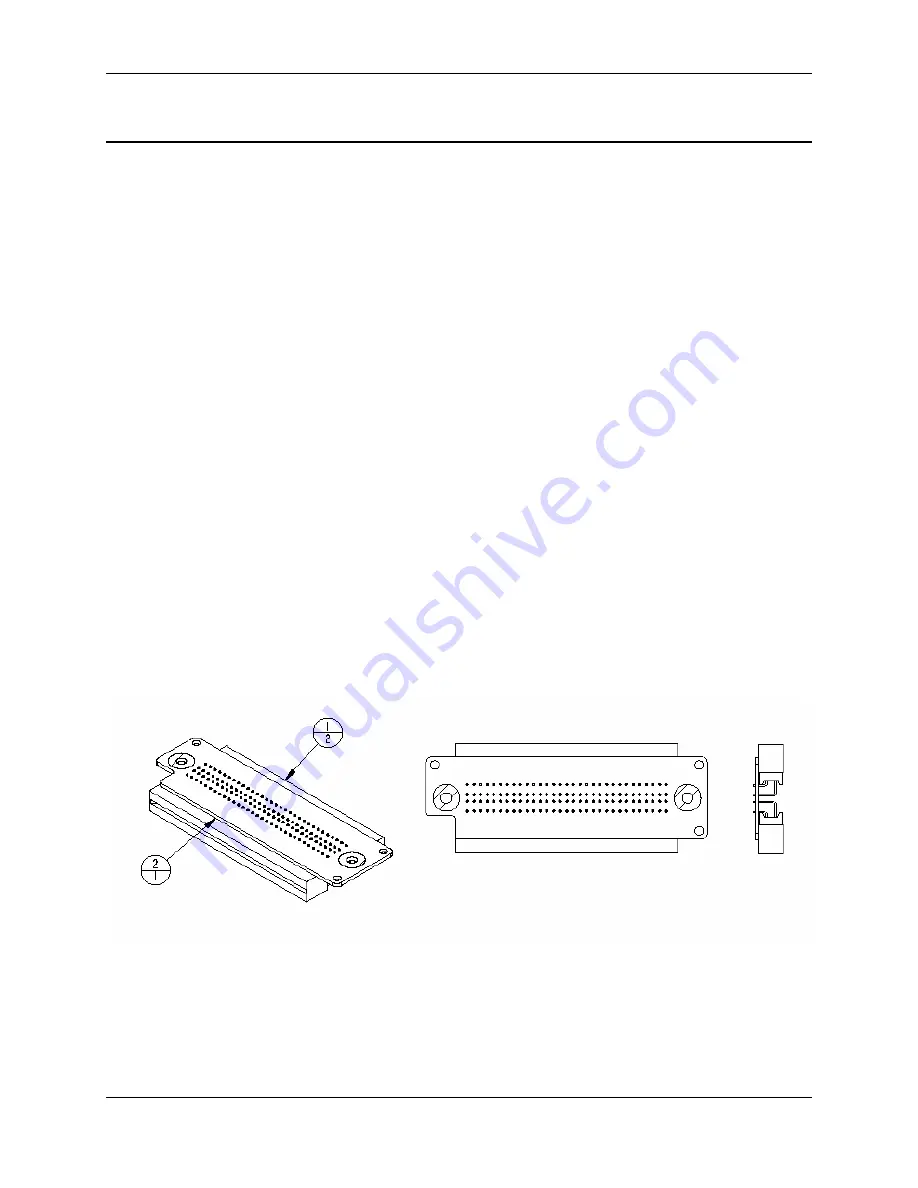
The power interconnect board is used to interconnect between the power supply and the
extended front panel board. Both the power supply and the front panel board have card-edge
fingers to interface to the card-edge connectors on the power interconnect system board.
Power passes from the 250 watt power supply through the power interconnect system board to
the extended front panel system board. Power is then distributed from the extended front panel
system board to the other system boards via discrete cables.
2/1 – Board
1/2 – AMP 532600-4 Connector, Card Edge, Right-Angle
Figure 5-1. Physical Layout of Power Interconnect System Board


