background image

Intel

®

 5100 MCH Chipset

Intel

®

 5100 Memory Controller Hub Chipset for Communications, Embedded, and Storage Applications

TDG

July 2008

4

Order Number: 318676-003US

Figures

1

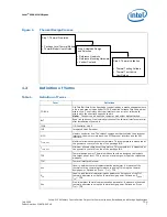
Thermal Design Process ............................................................................................. 7

2

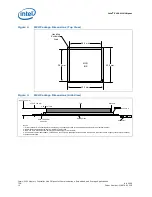
MCH Package Dimensions (Top View) ..........................................................................10

3

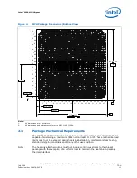
MCH Package Dimensions (Side View) .........................................................................10

4

MCH Package Dimensions (Bottom View) .....................................................................11

5

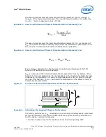
Processor Thermal Characterization Parameter Relationships ..........................................13

6

IHS Groove Dimensions.............................................................................................17

7

Orientation of Thermocouple Groove Relative to Package Pin ..........................................18

8

Bending Tip of Thermocouple .....................................................................................18

9

Securing Thermocouple Wires with Kapton Tape Prior to Attach ......................................19

10 Thermocouple Bead Placement ...................................................................................20
11 Positioning Bead on Groove .......................................................................................20
12 Using 3D Micromanipulator to Secure Bead Location......................................................21

13 Measuring Resistance between Thermocouple and IHS ..................................................21
14 Applying Adhesive on Thermocouple Bead....................................................................22
15 Thermocouple Wire Management in Groove..................................................................23

16 Removing Excess Adhesive from IHS...........................................................................23
17 Filling Groove with Adhesive ......................................................................................24
18 Torsional Clip Heatsink Measured Thermal Performance versus Approach Velocity .............25

19 AdvancedTCA* Torsional Clip Heatsink Volumetric Envelope for MCH Heatsink ..................26
20 Torsional Clip Heatsink Assembly................................................................................27
21 Isometric View of the CompactPCI* Reference Heatsink.................................................29

22 CompactPCI* Reference Heatsink Thermal Performance.................................................30
23 AdvancedTCA* Heatsink Assembly Drawing .................................................................32
24 AdvancedTCA* Heatsink Drawing................................................................................33

25 AdvancedTCA* Component Keepout Zone ....................................................................34
26 CompactPCI* Heatsink Assembly Drawing ...................................................................35
27 CompactPCI* Heatsink Drawing..................................................................................36

28 CompactPCI* Component Keepout Zone ......................................................................37
29 Torsional Clip Heatsink Clip Drawing ...........................................................................38
30 TIM2 Drawing ..........................................................................................................39

Tables

1

Definition of Terms .................................................................................................... 7

2

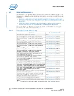
Related Documents.................................................................................................... 8

3

Intel

®

 5100 Memory Controller Hub Chipset Thermal Specifications.................................12

4

Required Heatsink Thermal Performance (

Ψ

CA

) .............................................................15

5

Thermocouple Attach Support Equipment ....................................................................16

6

Honeywell* PCM45F TIM Performance as Function of Attach Pressure ..............................28

7

Reliability Guidelines .................................................................................................29

8

Reliability Requirements ............................................................................................30

9

Mechanical Drawing List ............................................................................................31

10 MCH Torsional Clip Heatsink Thermal Solution ..............................................................40

Summary of Contents for WiFi Link 5100

Page 1: ...Order Number 318676 003US Intel 5100 Memory Controller Hub Chipset for Communications Embedded and Storage Applications Thermal Mechanical Design Guide July 2008 Revision 003US ...

Page 2: ...t notice Do not finalize a design with this information The products described in this document may contain design defects or errors known as errata which may cause the product to deviate from published specifications Current characterized errata are available on request Contact your local Intel sales office or your distributor to obtain the latest specifications and before placing your product or...

Page 3: ...oning and Preparation 18 5 1 5 Thermocouple Attachment to IHS 18 5 1 6 Curing Process 22 5 1 7 Thermocouple Wire Management 23 5 2 Power Simulation Software 24 6 0 Reference Thermal Solution 24 6 1 AdvancedTCA Reference Heatsink 25 6 1 1 Thermal Performance 25 6 1 2 Mechanical Design Envelope 25 6 1 3 Board level Components Keepout Dimensions 26 6 1 4 Torsional Clip Heatsink Thermal Solution Assem...

Page 4: ...23 17 Filling Groove with Adhesive 24 18 Torsional Clip Heatsink Measured Thermal Performance versus Approach Velocity 25 19 AdvancedTCA Torsional Clip Heatsink Volumetric Envelope for MCH Heatsink 26 20 Torsional Clip Heatsink Assembly 27 21 Isometric View of the CompactPCI Reference Heatsink 29 22 CompactPCI Reference Heatsink Thermal Performance 30 23 AdvancedTCA Heatsink Assembly Drawing 32 24...

Page 5: ...Release Information 0 0 POP L3 Closure Initial Documentation Typically Internal Only 0 1 0 4 When Needed Project Dependent Typically Internal Only 0 5 Design Win Phase First Required Customer Release 0 6 0 7 When Needed Project Dependent 0 7 Simulations Complete Second Recommended Customer Release 0 8 0 9 When Needed Project Dependent 1 0 First Silicon Samples Required Customer Release 1 1 1 4 Whe...

Page 6: ...e specified limits a system designer can ensure the proper functionality performance and reliability of the chipset Operation outside the functional limits can degrade system performance and may cause permanent changes in the operating characteristics of the component The simplest and most cost effective method to improve the inherent system cooling characteristics is through careful chassis desig...

Page 7: ...temperature This temperature is measured at the geometric center of the top of the package IHS Tcase_min Minimum allowed component temperature This temperature is measured at the geometric center of the top of the package IHS TDP Thermal design power Thermal solutions should be designed to dissipate this target power level TDP is not the maximum power that the chipset can dissipate TIM Thermal Int...

Page 8: ...8586 Dual Core Intel Xeon Processor 5200 Series Thermal Mechanical Design Guidelines http www intel com 318675 Dual Core Intel Xeon Processor LV 5138 in Embedded Applications Thermal Mechanical Design Guidelines http www intel com 315225 Intel 5000 Series Chipset Memory Controller Hub MCH Thermal Mechanical Design Guide http www intel com 313067 Intel 5100 Memory Controller Hub Chipset embedded Ex...

Page 9: ...H9 Family Thermal and Mechanical Design Guidelines Intel I O Controller Hub 9 ICH9 Family Thermal and Mechanical Design Guidelines http www intel com 316974 Quad Core and Dual Core Intel Xeon Processor 5000 Sequence with Intel 5100 Memory Controller Hub Chipset for Communications Embedded and Storage Applications Platform Design Guide Note 1 Quad Core Intel Xeon Processor 5300 Series Datasheet htt...

Page 10: ... 0 025 mm See note 3 Seating Plane 2 44 0 071 mm See note 1 Notes 1 Primary datum C and seating plan are defined by the spherical crowns of the solder balls shown before motherboard attach 2 All dimensions and tolerances conform to ANSI Y14 5M 1994 3 BGA has a pre SMT height of 0 5mm and post SMT height of 0 41 0 46mm 4 Shown before motherboard attach FCBGA has a convex dome shaped orientation bef...

Page 11: ...d shipping conditions and or any other use condition Note The heatsink attach solutions must not include continuous stress to the chipset package with the exception of a uniform load to maintain the heatsink to package thermal interface Figure 4 MCH Package Dimensions Bottom View Notes 1 All dimensions are in millimeters 2 All dimensions and tolerances conform to ANSI Y14 5M 1994 42 5 0 05 11 25 2...

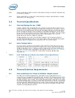
Page 12: ... proper operation and reliability of the Intel 5100 MCH Chipset the case temperatures must be at or between the maximum minimum operating temperature ranges as specified in Table 3 System and or component level thermal solutions are required to maintain these temperature specifications Refer to Section 5 0 Thermal Metrology on page 15 for guidelines on accurately measuring package case temperature...

Page 13: ...S is strongly dependent on the thermal conductivity and thickness of the TIM between the heatsink and device package ΨSA is a measure of the thermal characterization parameter from the bottom of the heatsink to the local ambient air ΨSA is dependent on the heatsink material thermal conductivity and geometry It is also strongly dependent on the air velocity through the fins of the heatsink Figure 5...

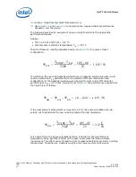
Page 14: ... provider would need to determine ΨCS performance for the selected TIM and mechanical load configuration If the heatsink solution were designed to work with a TIM material performing at ΨCS 0 20 C W solving from Equation 2 the performance needed from the heatsink is as follows If the local ambient temperature is relaxed to 45 C the same calculation can be carried out to determine the new case to a...

Page 15: ...couple For case temperature measurements the attached method outlined in this section is recommended for mounting a thermocouple Special care is required when measuring the case temperature TC to ensure an accurate temperature measurement Thermocouples are often used to measure TC When measuring the temperature of a surface that is at a different temperature from the surrounding local ambient air ...

Page 16: ...ing to the reference process 5 1 3 IHS Groove Cut a groove in the package IHS according to the drawing given in Figure 6 Note The center of the round at the end of the IHS groove should be at the center of the package Table 5 Thermocouple Attach Support Equipment Item Description Part Number Measurement and Output Microscope Olympus light microscope or equivalent SZ 40 Digital multi meter Digital ...

Page 17: ...Intel 5100 Memory Controller Hub Chipset for Communications Embedded and Storage Applications July 2008 TDG Order Number 318676 003US 17 Intel 5100 MCH Chipset Figure 6 IHS Groove Dimensions ...

Page 18: ...pecifications 3 Straighten the wire for about 38 mm 1 from the bead to place it inside the channel 4 Bend the tip of the thermocouple to approximately a 45 degree angle by 0 8 mm 0 030 from the tip Figure 8 5 1 5 Thermocouple Attachment to IHS Caution To avoid impact on the thermocouple during the SMT process reflow must be performed before attaching the thermocouple to the grooved MCH IHS 1 Clean...

Page 19: ...ope to perform this task Place a piece of Kapton tape to hold the wire inside the groove Figure 12 Refer to Figure 11 for detailed bead placement 6 Using the micromanipulator place the needle near the end of groove on top of the thermocouple Using the X Y and Z axes on the arm place the tip of the needle on top of the thermocouple bead Press down until the bead is seated at the end of the groove o...

Page 20: ...hipset Intel 5100 Memory Controller Hub Chipset for Communications Embedded and Storage Applications TDG July 2008 20 Order Number 318676 003US Figure 10 Thermocouple Bead Placement Figure 11 Positioning Bead on Groove ...

Page 21: ...t for Communications Embedded and Storage Applications July 2008 TDG Order Number 318676 003US 21 Intel 5100 MCH Chipset Figure 12 Using 3D Micromanipulator to Secure Bead Location Figure 13 Measuring Resistance between Thermocouple and IHS ...

Page 22: ...le by holding down the MCH unit and lifting the arm 4 Remove the Kapton tape and straighten the wire in the groove so that it is flat all the way to the end of the groove Figure 15 5 Using a blade shave excess adhesive above the IHS surface Figure 16 Note Take usual precautions when using open blades 6 Install new Kapton tape to hold the thermocouple wire down and fill the rest of the groove with ...

Page 23: ...r Communications Embedded and Storage Applications July 2008 TDG Order Number 318676 003US 23 Intel 5100 MCH Chipset 5 1 7 Thermocouple Wire Management Figure 15 Thermocouple Wire Management in Groove Figure 16 Removing Excess Adhesive from IHS ...

Page 24: ...d only be used to test thermal solutions at or near the thermal design power Real world applications may exceed the thermal design power limit for transient time periods For power supply current requirements under these transient conditions please refer to each component s datasheet for the ICC Max Power Supply Current specification Contact your Intel field sales representative to order the power ...

Page 25: ...n the boundary conditions the reference heatsink can meet the thermal performance needed to cool the Intel 5100 MCH Chipset in the AdvancedTCA form factor The heatsink performance versus airflow velocity is shown in Figure 18 The heatsink may be used in other form factors that can provide the required amount of airflow to meet the components thermal specifications 6 1 2 Mechanical Design Envelope ...

Page 26: ...tion are shown in Figure 25 This reference thermal solution has the same hole patterns as that of the Intel E7500 Series Chipset and Intel 5000 Series Chipset 6 1 4 Torsional Clip Heatsink Thermal Solution Assembly The reference thermal solution for the MCH is a passive extruded heatsink with a thermal interface It is attached using a clip with each end hooked through an anchor soldered to the boa...

Page 27: ...ling the MCH Appendix B lists a supplier for this extruded heatsink Other heatsinks with similar dimensions and increased thermal performance may be available A full mechanical drawing of this heatsink is provided in Appendix A 6 1 7 Mechanical Interface Material There is no mechanical interface material associated with this reference solution 6 1 8 Thermal Interface Material A thermal interface m...

Page 28: ...ve an End of Line thermal resistance of 0 345 C inches2 W and End of Life thermal resistance of 0 459 C inches2 W 6 1 9 Heatsink Clip The reference solution uses a wire clip with hooked ends The hooks attach to wire anchors to fasten the clip to the board See Appendix A for a mechanical drawing of the clip 6 1 10 Clip Retention Anchors For Intel 5100 MCH Chipset based platforms that have very limi...

Page 29: ... the heatsink clip are provided in Appendix A It uses the same spring clip retention and Honeywell PCM45F Thermal Interface Material TIM as the AdvancedTCA reference solution Figure 21 shows the isometric view of the CompactPCI reference heatsink Table 7 Reliability Guidelines Test1 Requirement Pass Fail Criteria2 Mechanical Shock 50 g board level 11 ms three shocks axis Visual Check and Electrica...

Page 30: ...tsink Thermal Performance 0 0 5 1 1 5 2 2 5 3 3 5 4 0 100 200 300 400 500 600 700 800 900 1000 1100 1200 Airflow Approach Velocity LFM Case To Am bient Therm al Characterization Param eter Ψ ca o C W CompactPCI Heatsink Table 8 Reliability Requirements Test1 Requirement Pass Fail Criteria2 Mechanical Shock 50 g board level 11 ms three shocks axis Visual Check and Electrical Functional Test Random ...

Page 31: ...s the mechanical drawings included in this appendix Table 9 Mechanical Drawing List Drawing Description Figure Number AdvancedTCA Heatsink Assembly Figure 23 AdvancedTCA Heatsink Figure 24 AdvancedTCA Component Keepout Zone Figure 25 CompactPCI Heatsink Assembly Figure 26 CompactPCI Heatsink Figure 27 CompactPCI Component Keepout Zone Figure 28 Reference Heatsink Torsional Clip Figure 29 TIM2 Figu...

Page 32: ...el 5100 MCH Chipset Intel 5100 Memory Controller Hub Chipset for Communications Embedded and Storage Applications TDG July 2008 32 Order Number 318676 003US Figure 23 AdvancedTCA Heatsink Assembly Drawing ...

Page 33: ...Intel 5100 Memory Controller Hub Chipset for Communications Embedded and Storage Applications July 2008 TDG Order Number 318676 003US 33 Intel 5100 MCH Chipset Figure 24 AdvancedTCA Heatsink Drawing ...

Page 34: ...ntel 5100 MCH Chipset Intel 5100 Memory Controller Hub Chipset for Communications Embedded and Storage Applications TDG July 2008 34 Order Number 318676 003US Figure 25 AdvancedTCA Component Keepout Zone ...

Page 35: ...tel 5100 Memory Controller Hub Chipset for Communications Embedded and Storage Applications July 2008 TDG Order Number 318676 003US 35 Intel 5100 MCH Chipset Figure 26 CompactPCI Heatsink Assembly Drawing ...

Page 36: ...Intel 5100 MCH Chipset Intel 5100 Memory Controller Hub Chipset for Communications Embedded and Storage Applications TDG July 2008 36 Order Number 318676 003US Figure 27 CompactPCI Heatsink Drawing ...

Page 37: ...ntel 5100 Memory Controller Hub Chipset for Communications Embedded and Storage Applications July 2008 TDG Order Number 318676 003US 37 Intel 5100 MCH Chipset Figure 28 CompactPCI Component Keepout Zone ...

Page 38: ...tel 5100 MCH Chipset Intel 5100 Memory Controller Hub Chipset for Communications Embedded and Storage Applications TDG July 2008 38 Order Number 318676 003US Figure 29 Torsional Clip Heatsink Clip Drawing ...

Page 39: ...Intel 5100 Memory Controller Hub Chipset for Communications Embedded and Storage Applications July 2008 TDG Order Number 318676 003US 39 Intel 5100 MCH Chipset Figure 30 TIM2 Drawing ...

Page 40: ... reference heatsink E45550 001 Cooler Master ECB 00590 01 GP Thermal interface C34795 001 Honeywell PCM45F Scott Miller 509 252 2206 scott miller4 honeywell com Paula Knoll 858 279 2956 paula_knoll honeywell com Heatsink attach clip D10234 001 CCI ACK Harry Lin USA 714 739 5797 hlinack aol com Monica Chih Taiwan 866 2 29952666 x1131 monica_chih ccic com tw Foxconn Bob Hall USA 503 693 3509 x235 bh...

Reviews: