Thermal/Mechanical Design Guide
7
Revision History
§
Document
Number
Revision
Number
Description
Revision
Date
321323
001
Public Release
March 2009
321323
002
Updates / additions in this revision include:
•
Changed to reflect addition of Intel® Xeon® Processor 5600 Series
•
Figure 1-1: replaced to show ILM load plate with cut out
•
Table 1-1: Updated References
•
Figures 2-4, 2-5: replaced to show ILM load plate with cut out
•
Section 2.3.4: Added Pick_and_Place_Removal_Tool
•
Section 3.1.1: fasteners are low carbon steel
•
Figures 3-1, 3-3, 3-4: replaced to show ILM load plate with cut out
•
Figure 3-2: replaced to show studs without knurled feature
•
Section 3.2: Changed torque from 8 ± 2 to 9 ± 1 inch-pounds
•
Table 4-3: min static load changed from 106 lbf to 100 lbf
•
Table 4-3: clarified Parameter as Target Pick and Place Cover allowable removal
force and updated the force associated with it
•
Table 5-1: Changed dP for 2U and Tower heatsink
•
Table 5-2: Added Boundary Conditions and Performance Targets for Intel®
Xeon® Processor 5600 Series
•
Figure 5-1: replaced curves for 1U with equations for 1U, 2U and Tower
•
Table 5-3: specified for Intel® Xeon® Processor 5500 Series Processors
•
Table 5-3: updated PSIca and dP values
•
Figure 5-3: replaced to show ILM load plate with cut out
•
Section 5.3: added Fastener sequencing statement (may mitigate against cross
threading).
•
Table 5-5: added Tcontrol Guidance for Intel® Xeon® Processor 5600 Series
•
Section 5.7: added Thermal Excursion for Intel® Xeon® Processor 5600 Series
•
Table 6-1: added reference to Table 5-2 for Intel® Xeon® Processor 5600 Series
•
Appendix A: added heatsink info for Intel® Xeon® Processor 5600 Series
•
Table A-4, A-5: updated supplier info
•
Appendix B: Added Figures B-27 to B-32 for 25.5mm heatsink
•
Table E-1: updated PSIca for 60W
•
Table E-2: added Boundary Conditions and Performance Targets for Intel®
Xeon® Processor 5600 Series
March 2010
Summary of Contents for X5550 - Quad Core Xeon
Page 8: ...8 Thermal Mechanical Design Guide ...
Page 12: ...Introduction 12 Thermal Mechanical Design Guide ...
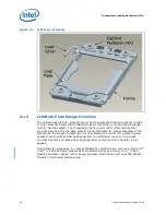
Page 24: ...Independent Loading Mechanism ILM 24 Thermal Mechanical Design Guide Figure 3 3 ILM Assembly ...
Page 26: ...Independent Loading Mechanism ILM 26 Thermal Mechanical Design Guide ...
Page 48: ...Component Suppliers 48 Thermal Mechanical Design Guide ...
Page 82: ...Mechanical Drawings 82 Thermal Mechanical Design Guide ...
Page 88: ...Socket Mechanical Drawings 88 Thermal Mechanical Design Guide ...


