Thermal/Mechanical Design Guide
91
Embedded Thermal Solutions
E
Embedded Thermal Solutions
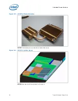
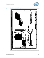
This section describes the LV processors and Embedded reference heatsinks for NEBS
(Network Equipment Building Systems) compliant ATCA (Advanced Telecommunications
Computing Architecture) systems. These LV processors are good for any form factor
that needs to meet NEBS requirements.
E.1
Performance Targets
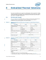
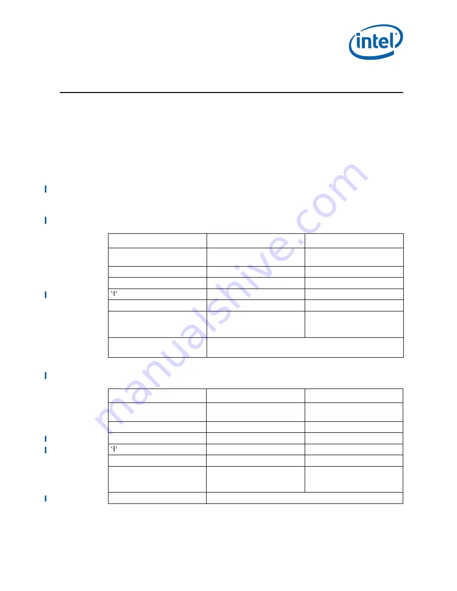
Table E-1
and
Table E-2
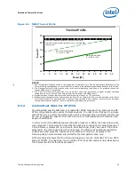
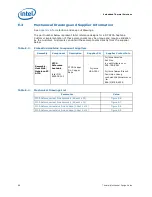
provide boundary conditions and performance targets for 1U
and ATCA heatsinks. These values are used to generate processor thermal
specifications and to provide guidance for heatsink design.
NOTES:
1. Local ambient temperature of the air entering the heatsink.
2. Max target (mean + 3 sigma + offset) for thermal characterization parameter (
Section 5.5.1
).
3. Reference system configuration. In a single wide ATCA blade the 60 W processor should be used in single
Table E-1.
Boundary Conditions and Performance Targets for Intel® Xeon® Processor
5500 Series
Parameter
Value
Value
Altitude, system ambient temp
Nominal/Short-term
Sea level, 40
o
C/55C
Sea level, 40
o
C/55C
TDP
60 W
38 W
T
LA
1,4
51.9/66.9
o
C
50/65
o
C
CA
2
0.336
o
C/W
0.532
o
C/W
System height (form factor)
3
1U (EEB) or ATCA
ATCA
Heatsink volumetric
1U (90 x 90 x 27) or Custom
ATCA (90 x 90 x 13mm + heat
exchanger)
ATCA (90 x 90 x 13 mm)
Heatsink technology
5
Cu base, Cu fins
Table E-2.
Boundary Conditions and Performance Targets for Intel® Xeon® Processor
5600 Series
Parameter
Value
Value
Altitude, system ambient temp
Nominal/Short-term
Sea level, 40
o
C/55C
Sea level, 40
o
C/55C
TDP
60 W
40W
T
LA
1,4
51.7/66.7
o
C
50/65
o
C
CA
2
0.306
o
C/W
0.548
o
C/W
System height (form factor)
3
1U (EEB) or ATCA
ATCA
Heatsink volumetric
1U (90 x 90 x 27) or Custom
ATCA (90 x 90 x 13mm + heat
exchanger)
ATCA (90 x 90 x 13 mm)
Heatsink technology
5
Cu base, Cu fins
Summary of Contents for X5550 - Quad Core Xeon
Page 8: ...8 Thermal Mechanical Design Guide ...
Page 12: ...Introduction 12 Thermal Mechanical Design Guide ...
Page 24: ...Independent Loading Mechanism ILM 24 Thermal Mechanical Design Guide Figure 3 3 ILM Assembly ...
Page 26: ...Independent Loading Mechanism ILM 26 Thermal Mechanical Design Guide ...
Page 48: ...Component Suppliers 48 Thermal Mechanical Design Guide ...
Page 82: ...Mechanical Drawings 82 Thermal Mechanical Design Guide ...
Page 88: ...Socket Mechanical Drawings 88 Thermal Mechanical Design Guide ...


