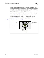
EMI and Mechanical Design Considerations
156
Design Guide
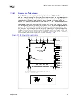
Figure 11-6. Retention Mechanism Placement and Keep-Out Overview
R etention Module 100 mils H eight
Retention
Socket Shown For R eference O nly
1.150 "
.
.000 "
3.200 "
1. 500 "
Retention Module
M ounting Holes
Socket PIN #1 Location
Maximum Component Height
0.35 " U nless O therwise Specified
+
.002
−
.001
∅
.159 "
Legend
EMI Pads
R etention M odule Mounting area, N o Component Placement Allowed
G round Frame Skirt 100 mils Max H eight Restriction Zone
G round Frame Skirt 150 mils Max H eight Restriction Zone
R etention M odule 180 mils Max H eight R estriction
R etention M odule 200 mils Max H eight R estriction
Summary of Contents for Xeon
Page 24: ...Introduction 24 Design Guide This page is intentionally left blank ...
Page 30: ...Component Quadrant Layout 30 Design Guide This page is intentionally left blank ...
Page 52: ...Platform Clock Routing Guidelines 52 Design Guide This page is intentionally left blank ...
Page 66: ...System Bus Routing Guidelines 66 Design Guide This page is intentionally left blank ...
Page 118: ...Intel 82870P2 P64H2 118 Design Guide This page is intentionally left blank ...
Page 146: ...I O Controller Hub 146 Design Guide This page is intentionally left blank ...
Page 148: ...Debug Port 148 Design Guide This page is intentionally left blank ...
Page 210: ...Schematic Checklist 210 Design Guide This page is intentionally left blank ...
Page 220: ...Layout Checklist 220 Design Guide This page is intentionally left blank ...
Page 222: ...Schematics 222 Design Guide This page is intentionally left blank ...


