Design Guide
171
Platform Power Delivery Guidelines
12.2.8
VCCA, VCCIOPLL, and VSSA Filter Specifications
VCCA and VCCIOPLL are required by the processor’s internal PLL. These voltages are created by
using a low pass filter on VCC_CPU. The processor has internal analog PLL clock generators that
require quiet power supplies for minimum jitter. Jitter is detrimental to a system; it degrades
external I/O timings, as well as internal core timings (i.e., maximum frequency). The filter
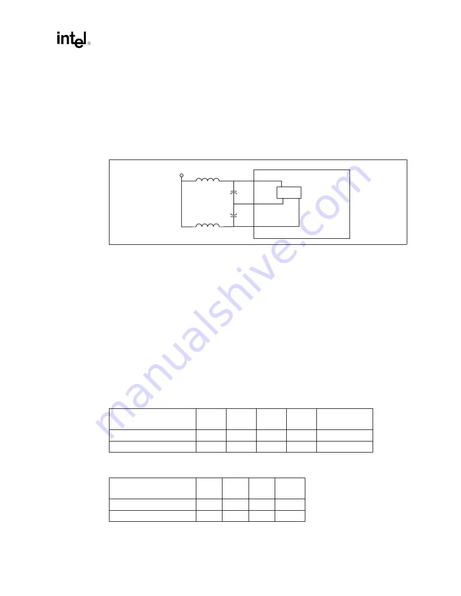
topology is shown in
. Not shown in the figure are the parasitics of connecting traces,
circuits, and components.
The function of the filter is two-fold. It protects the PLL from external noise through low-pass
attenuation; it also protects the PLL from internal noise through high-pass filtering. In general, the
low-pass description forms an adequate description for the filter. For simplicity, we are addressing
the recommendation for VCCA filter design. The same characteristics and design approach is
applicable for VCCIOPLL filter design.
Other requirements:
•
Use shielded type inductor to minimize magnetic pickup.
•
Filter should support DC current > 30 mA.
•
DC voltage drop from VCC_CPU to the processor interposer pin VCCA should be < 33 mV,
which in practice implies series R < 1.1
Ω
; this also means pass band (from DC to 1 Hz)
attenuation < 0.5 dB for VCC_CPU = 1.1 V, and < 0.35 dB for VCC_CPU = 1.7 V.
and
list some recommended components for the filter. Values in the table are
for reference only. For specific vendor information, contact your preferred vendor.
Figure 12-8. Processor Filter Topology
VCC_CPU
VCCA
VSSA
VCCIOPLL
L
Processor
Core
PLL
C
C
L
Table 12-3. Component Recommendation—Inductor
Part Number
(Reference Designator)
Value
Tol
SRF
Rated I
DCR
TDK MLF2012A4R7KT
4.7 µH
10%
35 MHz
30 mA
0.56
Ω
(1
Ω
max)
Murata LQG21N4R7K10
4.7 µH
10%
47 MHz
30 mA
0.7
Ω
(± 50%)
Table 12-4. Component Recommendation—Capacitor
Part Number
(Reference Designator)
Value
Tol
ESL
ESR
Kemet T495D336M016AS
33 µF
20%
2.5 nH
0.225
Ω
AVX TPSD336M020S0200
33 µF
20%
TBD
0.2
Ω
Summary of Contents for Xeon
Page 24: ...Introduction 24 Design Guide This page is intentionally left blank ...
Page 30: ...Component Quadrant Layout 30 Design Guide This page is intentionally left blank ...
Page 52: ...Platform Clock Routing Guidelines 52 Design Guide This page is intentionally left blank ...
Page 66: ...System Bus Routing Guidelines 66 Design Guide This page is intentionally left blank ...
Page 118: ...Intel 82870P2 P64H2 118 Design Guide This page is intentionally left blank ...
Page 146: ...I O Controller Hub 146 Design Guide This page is intentionally left blank ...
Page 148: ...Debug Port 148 Design Guide This page is intentionally left blank ...
Page 210: ...Schematic Checklist 210 Design Guide This page is intentionally left blank ...
Page 220: ...Layout Checklist 220 Design Guide This page is intentionally left blank ...
Page 222: ...Schematics 222 Design Guide This page is intentionally left blank ...


