Design Guide
83
Hub Interface
Hub Interface
7
7.1
Signal Naming Convention
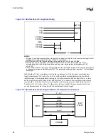
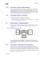
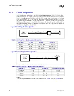
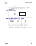
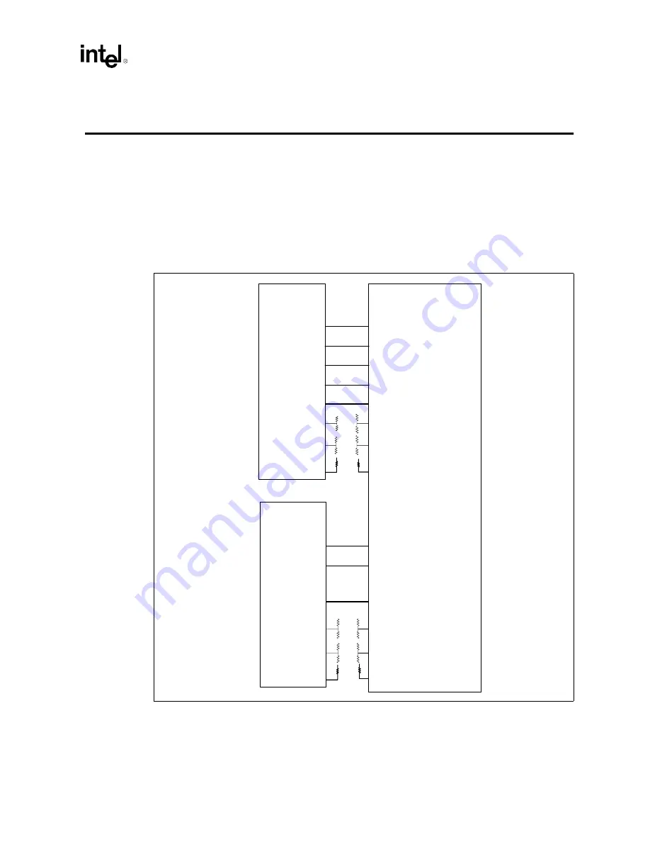
has the Hub Interface 2.0 and Hub Interface 1.5 signal naming convention for each
component. This figure is intended to give a quick naming cross reference to designers. The
specific guidelines and implementations on these signals are given in the following sections. Note
that throughout the document, the ‘x’ part of the MCH signal has been dropped for simplicity.
NOTES:
1. These signals have individual resistor dividers. For specific values, refer to
2. These signals have individual pull-up resistors. For specific values, refer to
.
3. Signal names for HI2.0 on the MCH: x = B, C, or D.
Figure 7-1. Signal Naming Convention on Both Sides of the Hub Interfaces
PUSTRBS
PUSTRBF
PSTRBS
PSTRBF
PUSTRBS_x
PUSTRBF _x
PSTRBS_x
PSTRBF_x
HI_[#]
HI[#]
HI2.0
HI_VSWING
1
HI_VREF
1
HI_RCOMP
2
HIRCOMP_x
2
HISWNG_x
1
HIVREF_x
1
HISWNG_A
1
HIVREF_A
1
HIRCOMP_A
2
HICOMP
2
HITERM
1
HIREF
1
HI_x[#]
HI_A[#]
HI_STBS
HI_STBF
HI_STBS
HI_STBF
HI1.5
MCH
Intel
®
P64H2
Intel
®
ICH3-S
Summary of Contents for Xeon
Page 24: ...Introduction 24 Design Guide This page is intentionally left blank ...
Page 30: ...Component Quadrant Layout 30 Design Guide This page is intentionally left blank ...
Page 52: ...Platform Clock Routing Guidelines 52 Design Guide This page is intentionally left blank ...
Page 66: ...System Bus Routing Guidelines 66 Design Guide This page is intentionally left blank ...
Page 118: ...Intel 82870P2 P64H2 118 Design Guide This page is intentionally left blank ...
Page 146: ...I O Controller Hub 146 Design Guide This page is intentionally left blank ...
Page 148: ...Debug Port 148 Design Guide This page is intentionally left blank ...
Page 210: ...Schematic Checklist 210 Design Guide This page is intentionally left blank ...
Page 220: ...Layout Checklist 220 Design Guide This page is intentionally left blank ...
Page 222: ...Schematics 222 Design Guide This page is intentionally left blank ...


