Intel
®
82870P2 (P64H2)
116
Design Guide
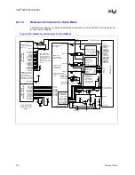
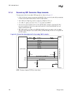
M66EN Isolation Switch Solution
One possible solution is to place a single 5
k
Ω
± 5% pull-up on the P64H2 side of the isolation
logic and a 5
k
Ω
± 5% pull-up on the slot side after the isolation logic, but with its own isolation
switch, which uses an inverted version of the bus enable control signal. This way, when the
isolation logic has the bus disconnected, the slot side will be pulled up with a 5
k
Ω
± 5% resistor.
When the isolation logic has the bus connected, the slot side resistor will be isolated, and the
M66EN line will be pulled up by the 5
k
Ω
± 5% pull-up on the P64H2 side of the isolation logic.
Using this method, the P64H2 would only be sinking through a single 5
k
Ω
resistor at any time and
would always be meeting the
PCI Local Bus Specification, Revision 2.2
on the M66EN pull-up
(
PCI Local Bus Specification, Revision 2.2, Section 7.7.7
). See
.
Figure 8-17. M66EN Isolation Switch Solution
PC
I
SL
O
T
M66EN
+3.3 V
+3.3 V
5 k
Ω
5 k
Ω
PCI Bus
Isolation Switch
M66EN
Isolation
Switch
HxM66EN
PxM66EN
Intel
®
P64H2
HxBUSEN#
Summary of Contents for Xeon
Page 24: ...Introduction 24 Design Guide This page is intentionally left blank ...
Page 30: ...Component Quadrant Layout 30 Design Guide This page is intentionally left blank ...
Page 52: ...Platform Clock Routing Guidelines 52 Design Guide This page is intentionally left blank ...
Page 66: ...System Bus Routing Guidelines 66 Design Guide This page is intentionally left blank ...
Page 118: ...Intel 82870P2 P64H2 118 Design Guide This page is intentionally left blank ...
Page 146: ...I O Controller Hub 146 Design Guide This page is intentionally left blank ...
Page 148: ...Debug Port 148 Design Guide This page is intentionally left blank ...
Page 210: ...Schematic Checklist 210 Design Guide This page is intentionally left blank ...
Page 220: ...Layout Checklist 220 Design Guide This page is intentionally left blank ...
Page 222: ...Schematics 222 Design Guide This page is intentionally left blank ...


