9
Terminals
Transmitter
Transmitter
Receiver
Receiver
Alimentation Alarm Tamper
Receiver
Transmitter
Receiver
IVA sensors can be used in conjunction with the Intelbras family of alarm panels. To connect these sensors to our line of
alarm panels, follow the steps:
» Supply the sensor with an external power supply DC 12 ~ 24 V or AC 11 ~ 18 V. If you do not have a source, use the
auxiliary output of our control units;
» Connect the
ALARM
output of the receiver to a corresponding terminal of the zone / sector alarm panel.
The relay output of the receiver can be configured via jumper in NC (normally closed) or NO (normally open). Adjustment
available on the rear of the jumper receiver plate (JP1).
Note.:
factory default: NC Normally closed
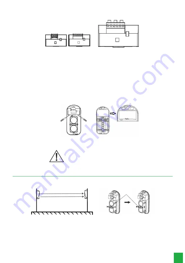
To change the jumper (JP1), open the receiver with the help of a screwdriver and unlock the rear cover.
Hangs
Hangs
Back
cover
Wiring / power ratio
Note:
variations in the sensor power input may occur due to the internal resistance in the cable being used.
Always check at the sensor input if the supply voltage
is between 12 - 24 Vdc or 11 ~ 18 Vac.
4. Beam alignment
1. Position the transmitter and receiver so that they are aligned and cover the area you want to protect. Remove the front
cover and power on the transmitter and receiver;
Receiver
Tr
ansmitter
Sight
2. Observe the other sensor through the holes located near the sights. The first adjustment must be visual, try to leave the
opposite sensor centered in the sight of the other sensor, as shown in the figure.
Note:
use a voltmeter to achieve a better adjustment - the higher the voltage level at the receiver output, the stronger the
signal level -, preventing false alarms caused by medium interference.


