background image

IA-3178-U2i


24 

www.intelligent-appliance.com


Specifications are subject to change without notice 

 
32-ch Relay 
USB or RS-232 Controlled 


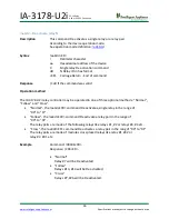
!aa2dddddddd – Set relays status 

Description 

This command defines module’s relay state. 


Syntax 

!aa2dddddddd <CR> 

Delimiter character 

aa 

Hexadecimal address of the device 

System control command 

Relay output activation command data for each nibble in hex format 

<CR>  Carriage Return - End of command 


Response 

|dddddddd 
if the command was valid and if FB messages are enabled 


Example 

Command: !

00280008000

 <CR> 

Response: |

 80008000

 <CR> 

 
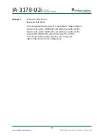
This command will activate relay #16 an #32 


This command does not function while “Relays pair” operation is selected.  
In this case command ‘!aa3dd’ and ‘!aa4dd’ should be used instead. 
 
Se

Register #51, bit 4=’1’

 for more information about Single/Pair operation.  


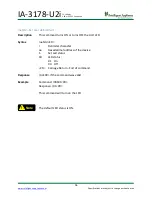
Note


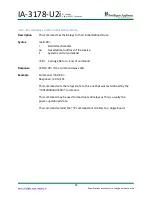
!


Summary of Contents for IA-3178-U2i

Page 1: ...User Manual Version 0616 www intelligent appliance com IA 3178 U2i 32 ch SPDT Power Relay Single or Pair Operation USB or RS 232 Controlled...

Page 2: ...ical support Intelligent Appliance delivers services via the internet The dedicated website offers large knowledgebase database that include full information for Development Engineers Installers in th...

Page 3: ...TATUS 18 AA50 GET DEVICE MODE REGISTER 50 19 AA51 GET DEVICE MODE REGISTER 51 20 AAID GET MODULE S ID NUMBER 21 AAS GET USER JUMPER USER LED AND VOLTAGE MONITOR STATUS 22 AAWDT GET WD2 COUNT DOWN VALU...

Page 4: ...round Loops and EMI RFI Interference while the second Watchdog task is providing a user defined way of handling Host computer and Communication failure The IA 3178 U2i is being widely supported by Mic...

Page 5: ...e 24V to 72VDC 90V to 240VAC IA 3178H Isolation Optic Communication Main COM Isolated USB or RS 232 DB9 Female Expansion Port Buffered RS 232 DB9 Male Factory Defaults Baud Rate 19 2bps Data bits 8 Pa...

Page 6: ...p Series USB Cable Include Caution possibility of electric shock Equipment protected throughout by double insolation or reinforced insolation Intelligent Appliance products are NOT authorized for use...

Page 7: ...fications are subject to change without notice 32 ch Relay USB or RS 232 Controlled Installation System Wiring DB9 Female or USB DB9 Male or USB DB9 Female DB9 Male DB9 Female 255 Host PC Chaining Dev...

Page 8: ...ignment J1 Main Port USB J2 Secondary Port RS 232 DB9 Female Pin Function 2 Tx 3 Rx 5 GND J3 Expansion Port RS 232 DB9 Male Pin Function 2 Rx 3 Tx 5 GND TB1 to TB8 Relay 1 to Relay 32 TB9 Voltage Moni...

Page 9: ...ent appliance com Specifications are subject to change without notice 32 ch Relay USB or RS 232 Controlled Relay Pinout SPDT Form C Channels 1 32 Terminal Relay Pin TB1 1 NO TB1 1 C TB1 1 NC TB8 32 NO...

Page 10: ...g operation modes 32 Single operated Relays Normal 32 31 30 29 28 27 26 25 24 23 22 21 20 19 18 17 1 2 3 4 5 6 7 8 9 10 11 12 13 14 15 16 16 Cross Pairs operated Relays Cross 32 31 30 29 28 27 26 25 2...

Page 11: ...ject to change without notice 32 ch Relay USB or RS 232 Controlled Isolated Line Monitor Input IA 3178 U2i 12 72 VDC IA 3178H U2i 90 240 VAC TB9 2 TB9 1 Internal Logic 12 to 72VDC 12 to 72VDC 90 to 24...

Page 12: ...a creation of new Serial COM that can be easily found on the Device Manager screen At this stage you can easily control the IA 3178 U2i I O s by either any serial control software or by the IA3000Util...

Page 13: ...ase www intelligent appliance com Handling IA 3000 Utility 1 Start the IA3000Util Utility by pressing Start Manu on the computer s main screen select All Programs and finally IA3000Util 2 Select the a...

Page 14: ...ifications are subject to change without notice 32 ch Relay USB or RS 232 Controlled 6 Once the device is selected its form will be shown on the control panel label 7 Left clicking the buttons will ac...

Page 15: ...AND OUTPUTS STATUS 18 AA50 GET DEVICE MODE REGISTER 50 19 AA51 GET DEVICE MODE REGISTER 51 20 AAID GET MODULE S ID NUMBER 21 AAS GET USER JUMPER USER LED AND VOLTAGE MONITOR STATUS 22 AAWDT GET WD2 C...

Page 16: ...tax aa0 CR Delimiter character aa Hexadecimal address of the device 0 Get device Model command CR Carriage Return End of command Response _nnnn CR if the command was valid _ Response delimiter nnnn A...

Page 17: ...xadecimal address of the device 1 Get device Version command CR Carriage Return End of command Response _nnnn CR if the command was valid _ Response delimiter nnnn A string containing the device versi...

Page 18: ...ce 2 Read I O status CR Carriage Return End of command This relay controller may by operated in two different methods 1 Normal 2 Relay pairs Register 51 bit 4 0 Register 51 bit 4 1 32 Relays 16 Relay...

Page 19: ...aa50 CR Delimiter character aa Hexadecimal address of the device 50 System Mode command CR Carriage Return End of command Response _dd CR if the command was valid dd Mode 00 FF 82 Enable BR change 02...

Page 20: ...gle Pair operation 4 10 1 16 Pairs 00 0 32 Single relays Relays Crossing Following Orientation 3 08 1 Crossing Pair aa5118 00 0 Following Pair aa5110 WD2 Host communication watchdog 2 04 1 Enabled 00...

Page 21: ...ontrolled aaID Get module s ID number Description This command reads the Device ID Syntax aaID CR Delimiter character aa Hexadecimal address of the device ID Command for read ID CR Carriage Return End...

Page 22: ...r character aa Hexadecimal address of the device S Read jumper led status CR Carriage Return End of command Response _dd CR if the command was valid _ Delimiter character dd Output digits A 1st Input...

Page 23: ...er character dd Output digits in HEX format Example Command 00WDT CR Response _12 CR In case that WD2 is Activated Response _20 WD2 ERR CR In case that WD2 is Not Activated In this example WD2 Count d...

Page 24: ...stem control command d Relay output activation command data for each nibble in hex format CR Carriage Return End of command Response dddddddd if the command was valid and if FB messages are enabled Ex...

Page 25: ...command was valid Operation method The IA 3178 U2i relay controller may be operated in one of three optional methods Normal Follow and Cross Normal the aa3dd CR command activate a single relay in the...

Page 26: ...and was valid Operation method The IA 3178 U2i relay controller may be operated in one of three optional methods Normal Follow and Cross Normal the aa4dd CR command De activate a single relay in the r...

Page 27: ...ommand dd Mode 00 FF 82 Enable BR change Bit 7 Bit 1 40 Eliminate Response Bit 6 20 Add device Address to response Bit 5 02 Report on command errors Bit 1 00 Normal CR Carriage Return End of command R...

Page 28: ...as Single relay or as a Relay Pair Syntax aa51dd CR Delimiter character aa Hexadecimal address of the device 51 System mode command dd Mode register 51 bit Value dd Function Relays Single Pair operati...

Page 29: ...118 CR Response 181 EE OK This command will set 16 pairs of Cross Module relays operation Operation of pair 1 00300 CR will activate relay 1 and 32 Operation of pair 2 00301 CR will activate relay 2 a...

Page 30: ...CR Delimiter character aa Hexadecimal address of the device 6 Change device baud rate command dd Two characters representing the desired baud rate 12 1200 24 2400 48 4800 96 9600 19 19200 default 38...

Page 31: ...ke sure setting mode register 50 value to its normal setting when done Syntax aa7dd CR Delimiter character aa Hexadecimal address of the device 7 Change device baud rate command dd New Hexadecimal add...

Page 32: ...ex format CR Carriage Return End of command Response n dd CR if the command was valid Example Command 00B124 CR Response 1 24 CR This command will activate relays 11 and 14 all other relays will be no...

Page 33: ...aE CR Delimiter character aa Hexadecimal address of the device E System control command CR Carriage Return End of command Response E DN CR if the command was valid Example Command 00E CR Response E DN...

Page 34: ...dddddd CR Delimiter character aa Hexadecimal address of the device E System control command d Relay output activation command data for each nibble in hex format CR Carriage Return End of command Respo...

Page 35: ...ommand d Relay output activation command data for each nibble in hex format CR Carriage Return End of command Response Mdddddddd CR if the command was valid Example Command 00M80000000 CR Response M80...

Page 36: ...d Description This command turns ON or turns OFF the ULD LED Syntax aaSdd CR Delimiter character aa Hexadecimal address of the device S Set Led status 0d LED status 01 On 00 Off CR Carriage Return End...

Page 37: ...2 Hex characters defines 10 to 256 Seconds CR Carriage Return End of command Response dd CR if the command was valid Example Command 00WDT20 CR Response 20 CR This command will activate WD2 relays pat...

Page 38: ...32 Controlled E Force initial state at all modules Description This command forces all modules on present chain into their pre defined initiate state Syntax E CR Delimiter character E System control c...

Page 39: ...elimiter character M Activate Relays per Memory Status CR Carriage Return End of command Response Relay state is set to predefine memory state no feedback message is returned Example Command 00M800000...

Reviews: