

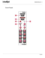


Mutamix Manual
v1.00
Installation
Intellijel
Eurorack
modules
are
designed
to
be
used
with
a
Eurorack-compatible
case
and
power
supply.
Before Your Start
Before
installing
a
new
module
in
your
case
you
must
ensure
your
case’s
power
supply
has
sufficient
available
capacity
to
power
the
module:
● Sum
up
the
specified
+12V
current
draw
for
all
modules,
including
the
new
one.
Do
the
same
for
the
-12
V
and
+5V
current
draw.
The
current
draw
will
be
specified
in
the
manufacturer's
technical
specifications
for
each
module.
● Compare
each
of
the
sums
to
specifications
for
your
case’s
power
supply.
● Only
proceed
with
installation
if
none
of
the
values
exceed
the
power
supply’s
specifications.
Otherwise
you
must
remove
modules
to
free
up
capacity
or
upgrade
your
power
supply.
You
will
also
need
to
ensure
you
have
enough
free
space
(hp)
as
well
as
free
power
headers
in
your
case
to
fit
the
new
module.
You
can
use
a
tool
like
ModularGrid
to
assist
in
your
planning.
Failure
to
adequately
power
your
modules
may
result
in
damage
to
your
modules
or
power
supply.
If
you
are
unsure,
please
contact
us
before
proceeding.
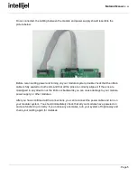
Installing Your Module
When
installing
or
removing
a
module
from
your
case
always
turn
off
the
power
to
the
case
and
disconnect
the
power
cable.
Failure
to
do
so
may
result
in
serious
injury
or
equipment
damage.
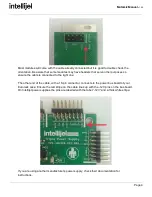
Ensure
the
10-pin
connector
on
the
power
cable
is
connected
correctly
to
the
module
before
proceeding.
The
red
stripe
on
the
cable
must
line
up
with
the
-12V
pins
on
the
module’s
power
connector.
The
pins
are
indicated
with
the
label
-12V,
a
white
stripe
next
to
the
connector,
the
words
“red
stripe”,
or
some
combination
of
those
indicators.
Page
3