


Intellipure © 2021 All rights reserved.
6
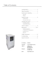
System Overview
COMPONENT DESCRIPTION
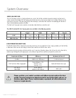
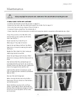
The 950P Portable DFS Air Cleaning System integrates the system components into a single, portable unit: the Prefilter,
V-Bank Main Filter and the High Energy Grid are accessible from the filter access door.
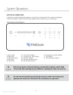
Electrical controls are located on the front of the unit. It consists of the Main Power ON-OFF switch with a Blue LED to
indicate High Voltage Power Supply power status, Blower Speed Status and Blower Speed Control Switch.
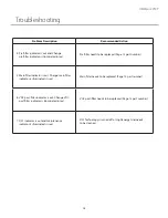
Replacement Filters
Efficiency
Replacement Period*
Prefilter
MERV-8 (35% Efficiency)
1-2 times per year
VOC Post Filter (When equipped)
Formaldehyde > 99%
Benzine > 99%
Toluene > 99%
Optional V-Bank: once a year
DFS V-Bank
Main Filter
99.99% Efficient
(down to .007 microns)
once a year
UNIT DESCRIPTION
The Air Cleaning System is a high performance system that utilizes patented award-winning Disinfecting Fil-
tration System technology. DFS technology electrically converts a low pressure drop filter to high efficiency while
retaining the low pressure drop and longer life advantages of the base filter material. This technology has also been
shown to inhibit bacteria growth on the filter.
The Electrical Components are located in an enclosed electrical box inside the unit.
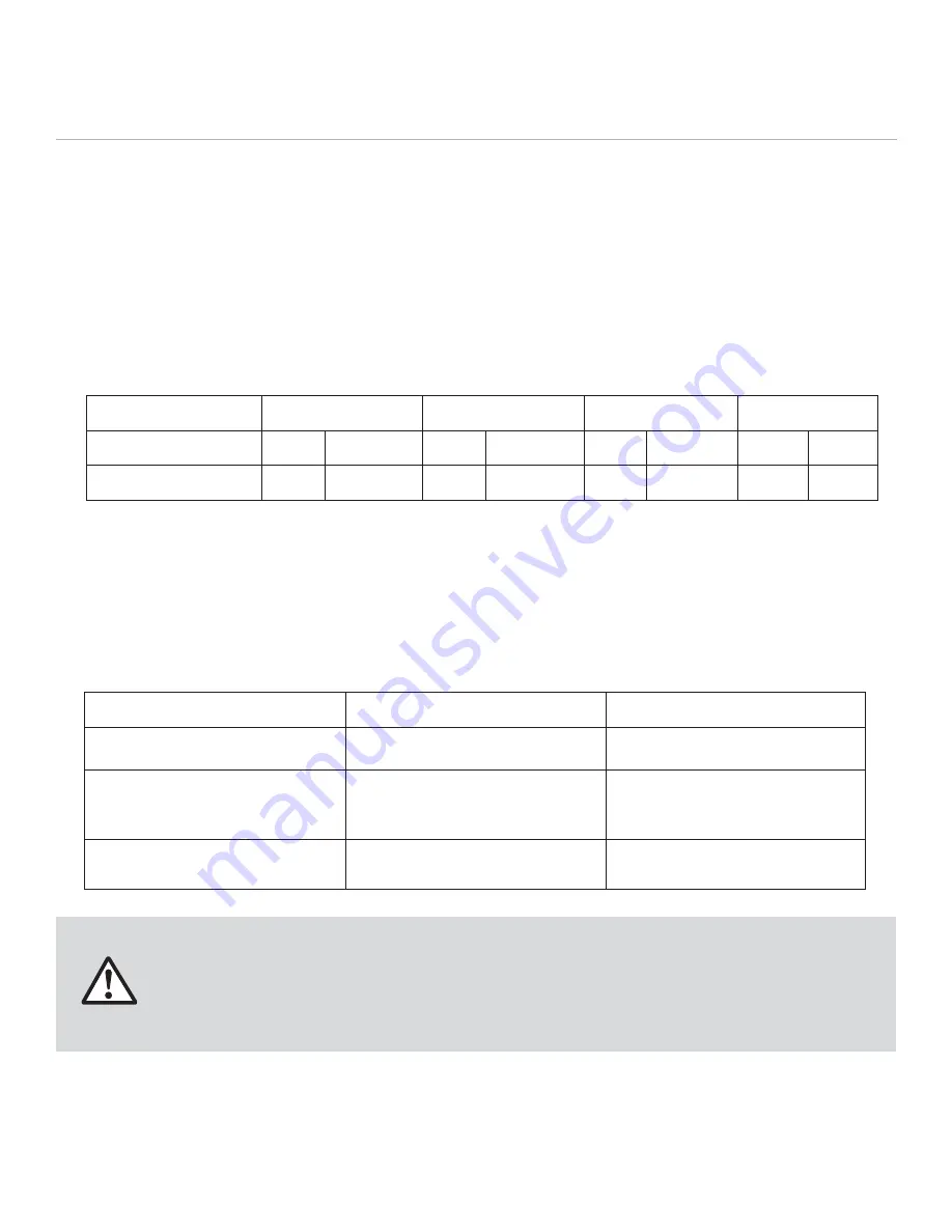
The 950P Portable DFS Air Cleaning System is available in the following models:
Height
Width
Depth
Weight
950P
44in
1,118mm
18in
457mm
28in
711mm
155 lb
70 kg
With VOC Filter
57in
1,448mm
18in
457mm
28in
711mm
215 lb
98 kg
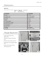
Please confirm your model number and follow the instructions for that
model. The electrical power requirements for each individual unit are on
the data plate label. These requirements supersede all other inferences
to power requirements.


