background image

Intellipure 950P

9

System Operation

POWER ON /OFF  

1.  When unit is plugged in, control goes through self-diagnosis and then returns to the last setting before power was lost. 

2.  When unit is off (and plugged in), only the power button is dimly lit.

SPEED CONTROL 

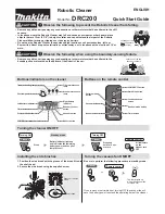
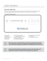
1.  When unit is turned on, Power Button, Speed Bar, DFS and Filter Lights will be illuminated white.

2.  Touch the fan speed bar to increase or decrease fan speed by increments of four. 

3.  For fine-tuning Speed: 

a.  Touch the small fan symbol (button b in On-board Touch Pad Diagram) to decrease fan speed by 2 increments. 
b.  Touch the large fan symbol (button d in On-board Touch Pad Diagram) to increase fan speed by 2 increments.

SLEEP MODE 


1.  Adjust to desired speed for Sleep Mode.  Press & hold Sleep Mode Button for 5 seconds to activate Sleep Mode. 

2.  When Sleep Mode is activated, the whole user interface will dim to low. Only the Power Button and Sleep Mode Button 


are lit. The unit will remain running at the speed set before Sleep Mode was activated.

3.  To deactivate Sleep Mode, touch anywhere in the speed bar. 

TURBO MODE 

1.  Touch Turbo Mode button to activate Turbo Mode. 

2.  When activated, all buttons on the On-board Touch Pad are illuminated white. 

3.  To deactivate Turbo Mode, touch anywhere in the speed bar. 

FILTER INDICATOR 1/2/3

1.  When unit is operating properly, the filter indicators are illuminated white. 

2.  When filter lifespan has been reached, filter indicator goes out and change filter indicator turns red. 

3.  Filter light can be reset by holding the respective filter light button for 5 seconds. When filter indicator quickly flashes  


6 times, the timer is successfully reset.

DFS INDICATOR

1.  When unit is on and DFS is operating properly, the indicator lit in white. 

2.  When DFS needs maintenance, DFS will automatically turn off. When DFS is turned off, indicator turns RED. 

3.  DFS can be activated / deactivated by touching DFS button. When DFS is deactivated, the DFS indicator turns off and   


DFS deactivation indicator turns red. 

Summary of Contents for 950P

Page 1: ...Operation Manual Intellipure 950P COMMERCIAL PORTABLE AIR PURIFICATION SYSTEM ...

Page 2: ......

Page 3: ...om Limited Warranty 4 Safety Precautions 5 Receiving and Unpacking 5 Receiving Storage System Overview 6 Unit Description Component Description Installation Procedures 7 Power Requirements Location Determination System Operation 8 Maintenance 10 13 Prefilter Replacement V Bank Main Filter Replacement Cleaning the Unit Parts List Voltage Adjustments 13 Troubleshooting 14 System Schematic 15 ...

Page 4: ...IPPED TO OR FROM THE FACTORY OR DESIGNATED SERVICE CENTER IN CONNECTION WITH WARRANTY CLAIMS NOR DOES IT APPLY TO ANY DAMAGES OCCURRING DURING SUCH SHIPMENT C This Limited Warranty does not apply to labor for installation removal re installation and or travel or ship ping expenses and related expenses This Limited Warranty does not apply to replaceable filters LIMITATIONS Intellipure shall not be ...

Page 5: ...rrosion and excessive heat cold Must install the Prefilter andV Bank Main Filter before turning on the unit Safety Precautions This symbol will be used throughout this manual to indicate safety checkpoints Failure to heed these warnings and notices may result in damage to the unit and or injury to personnel SAFETY PRECAUTIONS Personnel who will operate this system or those who will perform mainten...

Page 6: ...icrons once a year UNIT DESCRIPTION The Air Cleaning System is a high performance system that utilizes patented award winning Disinfecting Fil tration System technology DFS technology electrically converts a low pressure drop filter to high efficiency while retaining the low pressure drop and longer life advantages of the base filter material Thistechnologyhasalsobeen showntoinhibitbacteriagrowtho...

Page 7: ...purifier anywhere in the room and on a flat and level surface to allow continuous airflow to the bottom intake and out the top outlet grill For best performance it is recommended to place the air purifier at least two 2 feet from walls and other obstructions Do not place the air purifier where drapes or other objects block airflow Always lock both casters Do not run power cord under carpeting or n...

Page 8: ... speed e Turbo mode f 1 VOC Pre filter indicator f 2 Change VOC pre filter indicator g 1 Main filter indicator g 2 Change main filter indicator h 1 VOC post filter indicator h 2 Change VOC post filter indicator i 1 DFS indicator i 2 DFS deactivation indicator Disconnect power to the unit before servicing Moving Parts inside Wait 30 seconds after turning the unit off before opening the Filter Acces...

Page 9: ...n and Sleep Mode Button are lit The unit will remain running at the speed set before Sleep Mode was activated 3 To deactivate Sleep Mode touch anywhere in the speed bar TURBO MODE 1 Touch Turbo Mode button to activate Turbo Mode 2 When activated all buttons on the On board Touch Pad are illuminated white 3 To deactivate Turbo Mode touch anywhere in the speed bar FILTER INDICATOR 1 2 3 1 When unit ...

Page 10: ...h the direction of the air flow label fig 3 Ensure the Prefilter is firmly seated unit will not turn on without installing Prefilter correctly Return the filter access door to the unit fig 4 and fig 10 threaded pin shall be positioned into the hole of the control panel to activate safety switch The unit will not operate without safety switch activated When replacing filters use only Intellipure ce...

Page 11: ... Main Filter fig 9 and apply High Energy Grid to the new filter Secure the High Energy Grid to the new V Bank Main Filter by turning and locking three panel clips fig 8 Slide theV Bank Main Filter and HighEnergyGrid Assemblybackintotheunit Pay attention to the Flow Direction Arrow on the filter the arrow should point towards the Supply Outlet end of the unit LockV bank filter with a flat screw dri...

Page 12: ...xtreme cases it may be necessary to remove the wires from the springs attached at each end to the power distribution bars thus allowing complete access to the inside of the High Energy Grid assembly for cleaning as previously described It is recommended that the manufacturer be contacted for detailed instructions should this step appear necessary Vacuum the bottom of the filter seal plate section ...

Page 13: ...ten wire WH611 Optional Part Number VOC Filter 2000 VOC Cartridge Maintenance PARTS LIST Order all parts by contacting Phone No 315 298 2904 1 800 843 3860 Fax No 315 298 6992 Email info intellipure com VoltageAdjustment In order to change the incoming voltage setting Unplug the unit Remove the front door Fig 1 Remove the electrical panel cover Fig 2 Slide voltage switch to appropriate voltage Fig...

Page 14: ...ded Action 1 Unit will not turn ON a Ensure power cord is plugged in electrical outlet is energized b Check fuse located on the bottom of the unit Check if fuse was blown c Ensure Pre filter was installed d Ensure V Bank Main Filter is locked correctly fig 6 e Ensure High Energy Wire is connected fig 5 2 The unit turns ON but no air blows out Turn off unit and unplug the power wait 2 minutes and r...

Page 15: ...in filter indicator is out Change main filter indicator is illuminated in red Main filter needs to be replaced Page 13 part number 6 VOC post filter indicator is out Change VOC post filter indicator is illuminated in red VOC post filter needs to be replaced Page 13 part number 7 DFS indicator is out and maintenance indicator is illuminated in red DFS Technology is turned off or High Energy Grid ne...

Page 16: ...intellipure com ...

Reviews: