background image


5


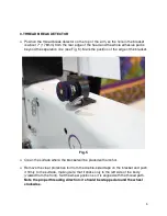
3. THREAD BREAK DETECTOR


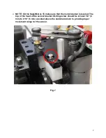
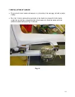
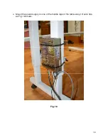
Position the thread break detector on the top of the arm, so the hole in the bracket 
is about 7" (178mm) from the rear edge of the head and the whole adhesive pad is 
beyond the separation line (see Fig. 5). Mark the position of the edge of the bracket. 


Fig. 5 


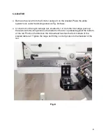
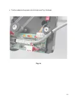
Clean the surface where the bracket will be placed with alcohol. 


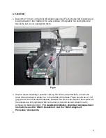
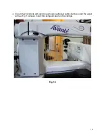
Remove the clear protective foil from the double-sided tape on the bracket and push 
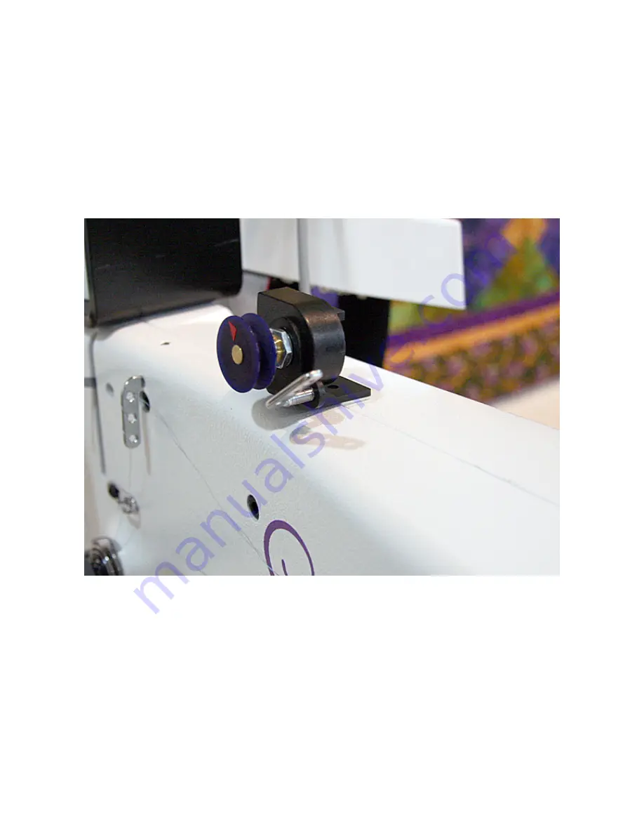
it firmly to the surface, making sure that it sticks only to the left side of the body 
(viewed from the front). Set the wheel position so it is aligned with the thread path. 

Note the proper threading direction: it should be wrapped around the wheel 
clockwise. 


Summary of Contents for HQ-AVANTE 03.25.16

Page 1: ...tor on the side of the head Plug in the IQ switch cable s in line adapter Reinsert the flat cable Fig 1 Remove the front control box from the handle assembly and place it on the top of the handle so the cable does not get stretched Mount the extender brackets as Fig 2 shows Mount the control box on the bottom of the extender brackets ...

Page 2: ...2 Fig 2 Remove the two front screws from the handle Mount the computer support plate on the top of the handle using 2 pcs M6 X 60 mm bolts and serrated spring washers ...

Page 3: ...3 Remove the yellow thumbscrews flip up the computer cradle and mount the computer bracket on the support plate using 4 pcs 10 32x1 4 button head screws Fig 3 Put back the yellow thumbscrews ...

Page 4: ...4 Fig 4 Plug in the switch cable in the six pin connector as shown on Fig 4 Dock the computer and adjust the height and angle of the computer docking station Tighten the four screws at that position ...

Page 5: ...ition of the edge of the bracket Fig 5 Clean the surface where the bracket will be placed with alcohol Remove the clear protective foil from the double sided tape on the bracket and push it firmly to the surface making sure that it sticks only to the left side of the body viewed from the front Set the wheel position so it is aligned with the thread path Note the proper threading direction it shoul...

Page 6: ... utilizing the slots on the brackets so both the drive roller and sensor wheel run in the middle of the track There should be a 1 16 gap about one credit card thickness between the drive roller and the track when all the screws are fully tightened Move the drive roller and sensor wheel in out to achieve the best alignment For detailed installation alignment and adjustment instructions see the SM V...

Page 7: ...make sure that the motor bracket is leveled The top of the head of the sensor bracket limiting screw should be at least 1 8 3 mm to 2 10 5 mm elevated above the aluminum block to provide proper movement range for the sensor Fig 7 ...

Page 8: ...he front of the right carriage rail at about 5 1 2 from the front edge push up the aluminum mounting block so the bottom of the slot is pressed against the bottom of the rail Position the block so the drive wheel touches the front surface of the slanted table rail Tighten the large bolt firmly so its tip cuts into the material of the rail Fig 8 ...

Page 9: ...s shown on Fig 9 There should be a 1 16 gap about one credit card thickness between the drive roller and the track when all the screws are fully tightened Move the drive roller and sensor wheel in out to achieve the best alignment For detailed installation alignment and adjustment instructions see the SM V3 Installation and the Motor Alignment Procedure documents ...

Page 10: ...der to stop the plastic insert from moving inside the aluminum track bolt down both ends with the included 6 32 X screws Drill and tap holes at from each edge of the insert and secure it with the screws Fig 10 ...

Page 11: ...l on the right thoroughly with alcohol Remove the protective foil and mount one of the rubber strips on the top of the rail Move the machine all the way to the left viewed from the back Stop where the X motor s sensor wheel still stays on the track Clean the top of the rail next to the carriage wheel on the left Remove the protective foil and mount the other rubber strip on the top of the rail Fig...

Page 12: ... 6 JUNCTION BOX Mount the junction box in the existing holes on the rear crossbar of the carriage using two 20 X screws as shown on Fig 12 Arrange the wires and the stitch regulator cable as shown Fig 12 ...

Page 13: ...secure it on the side of the carriage rail with a cable clamp Run the Y motor cable at the right side of the machine viewed from the back under the control box along the side of the lower arm Hold the cable with one adhesive cable clamp as Fig 13 shows Fig 13 ...

Page 14: ...14 Clean their locations with alcohol and place adhesive cable clamps under the upper arm as Fig 14 shows Insert the computer cable in the clamps Fig 14 ...

Page 15: ...15 Connect the computer power and communication connectors to the docking station as Fig 15 shows Plug in the thread break detector cable Fig 15 ...

Page 16: ...ower cable to the power supply BLACK wire to the negative terminal the wire with the in line diode to the positive terminal Fig 16 Put back the protective cover For strain relief tie the cable to the hole on the side of the power supply with wire tie Plug in the AC adapter jack ...

Page 17: ...17 Fig 17 ...

Page 18: ...18 Mount the power supply on one of the middle legs of the table using 14 wire ties as Fig 18 shows Fig 18 ...

Page 19: ...19 Tie the cables to the posts on both motors as Fig 19 shows Fig 19 ...

Page 20: ...20 Put the plastic covers on the motors Pull up the cable in the slot at the side of the cover as Fig 20 shows Fig 20 ...

Page 21: ...librate the sensor wheels following the on screen instructions Go to System Interface Setup Test Enter all the settings shown on the screenshot that was taped to the top of the box containing the tablet and the docking station Ask the customer to set her his preference for half or full cycle when the single stitch switch is pushed Set the Single Stitch Phase accordingly If the half stitch option i...

Page 22: ...22 COPY THE LOGS AND POST THE logs tar gz FILE TO THE SUPPORT PAGE OF www intelliquilter com ...

Reviews: