IntelliSAW IRM-48 Reader
Installation Manual
Page 16 of 28
IRM-48 Reader
910.00371.0001
AC/DC
Power
Supply
N L
V+ V-
N
L
Input Power
2-pole
Circuit
Breaker
1
3
2 4
IntelliSAW
Reader
V+ V- FE
Low-voltage
Compartment FE
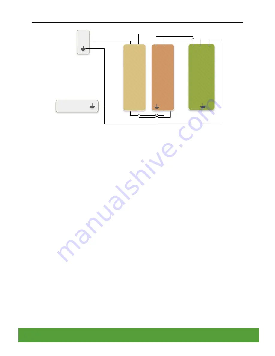
Figure 10: IntelliSAW Reader Recommended Power Wiring
4.1.1.1 Local versus bussed DC power
IntelliSAW recommends the use of a DC power supply in the same low-voltage compartment as
the reader. This is the simplest and most flexible option. It is possible to run a DC power bus
alongside the RS485 bus, however, this option requires careful consideration of the wire
diameter. This method also increases the likelihood of EFT or surge voltages along the DC bus.
4.1.1.2 DC power wire diameter considerations
Power connections are recommended to be a minimum 18 AWG, tin-coated, soft drawn copper
per ASTM B8, Class B stranding, 300V rated. Insulation shall be EP (ethylene propylene) or
EPCP (ethylene propylene chlorosulfonated polyethylene compound).
If bussed power is being considered, the wire gauge must be selected to prevent excessive
voltage drop between the DC power source and the reader that is electrically farthest from the
source. The larger wire diameter required could force the use of a custom cable for DC power
as the power bus wire cannot be the same gauge as the communications bus (RS485). Most
standard RS485 bus installations use wire diameters of about 0.5mm or 24 AWG; this wire size
may be too small to properly support DC power to all the readers if there are many readers a
bus.
4.1.1.3 Functional Earth wiring
Functional earth (FE) connection should always be installed b
etween the reader’s FE terminal,
FE post, and the FE connection in the low-voltage compartment
.
FE at the cable connection
shunts transients at the cables, while case ground provides both RF shielding and safety
against induced voltages on air interface cables.


