2
3. Connections & Buttons Description
3.1 Connections
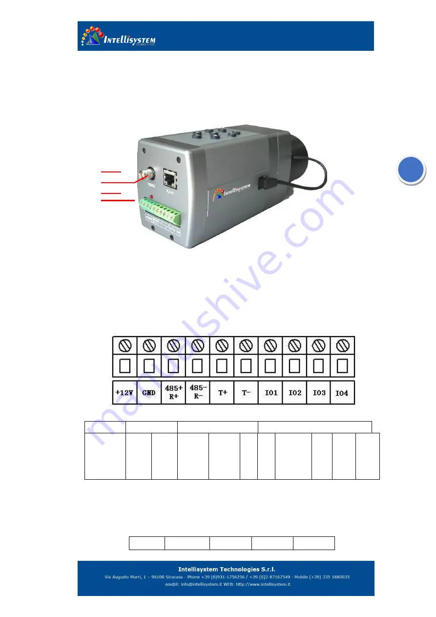
Figure 3.1
1.
Ethernet Port:
For data and information transfers.
2.
Analog Video Output Connector:
Connect large monitors for viewing.
3.
Power Supply Connector:
Connect to power supply
4.
Serial Communication and I/O Port:
Digital (TTL) output/input, YUN terrace
communication and user-defined pins.
IO port output function recommended connection.
Output definition
(
form left to right
):
Item
Power supply
Serial port
Common IO and COM ports
definition
+12V
GND
RS485+
/R+
RS485-
/R-
T+
T-
GPIO1
(
voice
alarm
output
)
GPI
O2
GPI
O3
COM
Description
:
1.
Power in
:
+12V
,
GND
2.
Serial port
RS485 output
:
RS485+
,
RS485-
4 terminals“RS485+/R+
,
RS485-/R-
,
T+,T-,”configuration:
Terminal RS485+/R+
RS485-/R-
T+
T-
2
1
3
4


