background image


Hardware Quick Installation Guide 

1. 

Introduction 


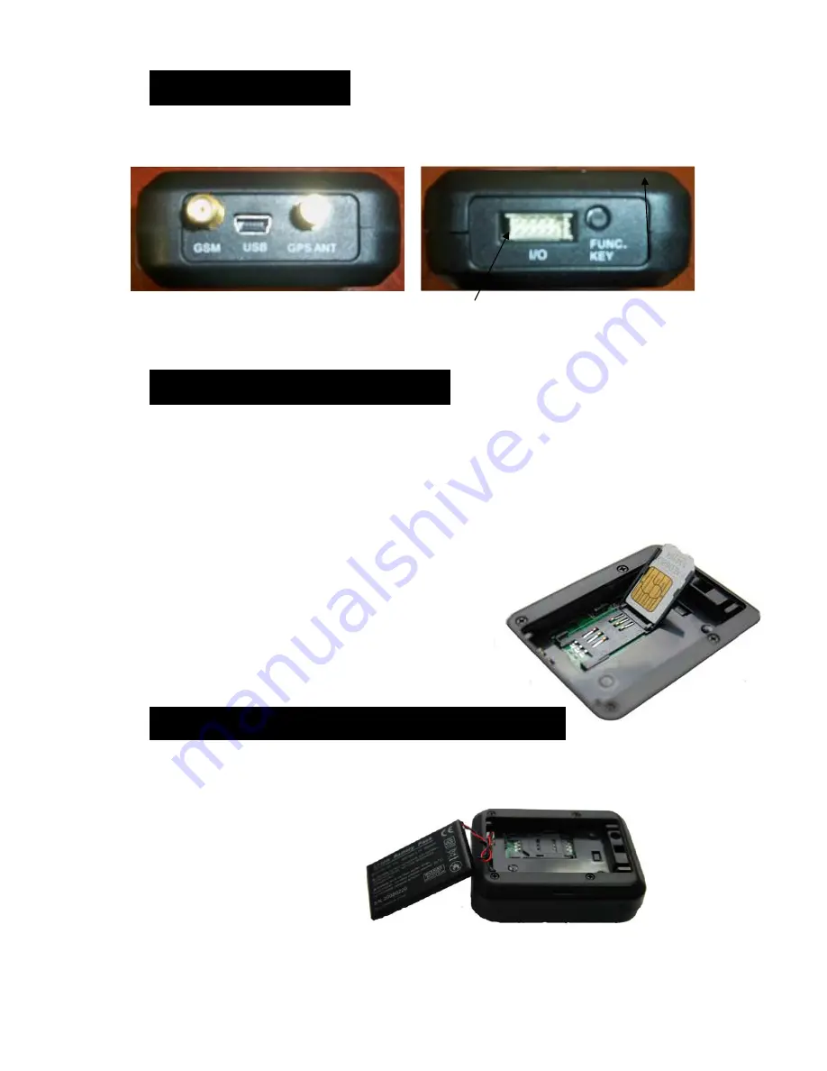
                      Front Panel:                                          Rear Panel: 


Power Connector    Function Key 


2. 

Insert the SIM Card


Please follow the steps below to insert the SIM Card correctly. 

a.


Ensure the Sim Card is NOT pin locked  

b.


Unscrew the back cover of device and pull out the lid by sliding lock to the right. 

c.


Lift up the battery (if the battery is connected to the device) 

d.


Unlock the SIM card slot by sliding the holder toward the “OPEN” direction. 

e.


Place the SIM card into the SIM card holder. 

f.


Lock the SIM card slot by sliding the holder toward the “LOCK” direction. 

g.


Then, put back the battery and screw the back  cover of the device. 

  
Please ensure the SIM card is well placed in the holder and  
well contacted; otherwise, the  device might not detect  
the SIM card successfully. 


3. 

Insert the backup battery 

Please follow the steps below to insert the backup battery correctly. 
a. Unscrew the back cover of device and pull out the lid by sliding lock to the right. 
b. Connect the cable to the socket in the corner and place the battery . 
c. Then, put the cover of the device back and screw it in. 


Summary of Contents for IT-123

Page 1: ...Intellitrac IT 123 Device ID _______________________ Device PIN ___________ IntelliTrac 11 Scholar Drive Bundoora 3083 Victoria Australia Phone 03 9467 6188 or 1300 767 492 www intellitrac com au ...

Page 2: ...direction e Place the SIM card into the SIM card holder f Lock the SIM card slot by sliding the holder toward the LOCK direction g Then put back the battery and screw the back cover of the device Please ensure the SIM card is well placed in the holder and well contacted otherwise the device might not detect the SIM card successfully 3 Insert the backup battery Please follow the steps below to inse...

Page 3: ...ition Source This is a 12 volt power source when the Vehicle is running and switches to ground or 0 volt when the vehicle is turned off GPS and GSM Antennas must be connected to the relevant connectors See Front Panel The GPS and GSM antennas must be installed at least 60 cm apart The GPS antenna must be mounted so that the black plastic face has a clear view of the sky and is not obstructed by me...

Page 4: ...l Master Phone is the phone number of the phone you are using to send this sms Example WP commtype 0000 1 0412345678 The IT 123 will send a return confirmation SMS to your master phone number as follows OK COMMTYPE 1 0412345678 0 0 0 0 0 0 0 0 0 0 Step 2 Setup the IT 123 Time Zone This defines the time zone of the IT123 If you do not set this command the IT 123 will report all positions using GMT ...

Page 5: ...678 0400123456 04011253456 Step 4 Setup the IT 123 VIP Number Selection This defines the telephone numbers that you can easily select or change from those defined in step 3 SMS the following command to the phone number in the IT 123 WP VPOS PIN 2 Selection Where PIN is the allocated pin of the device as defined on the front page of this manual Example WP VPOS 0000 2 1 Selects only 1st number defin...

Page 6: ...obile phone carrier Step 2 If the IT 123 recognises your number as a programmed VIP number it will answer the call after 2 3 rings and immediately hang up Step 3 The IT 123 will send a location SMS to all VIP SMS Phones When you receive the SMS simply click on the Google link and a Google map will open showing the location of the IT 123 Dial Receive SMS Click on Link View Map on Phone ...

Reviews: