background image

7-4

7-3

2

1

7-

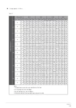
Curve diagr ram,   air flow volumn.

ons (60Hz) 

ons (60Hz) 

ons (60Hz) 

ons (60Hz) 

14 

I&O manual 


Fig.7-

7.5 T

Fig.

10 T

25 

Static pressure(Pa) 

Air volume(CFM) 

2500 2600 2700 2800 2900 3000 3100 3200 3300 3400 

50 

75 

100 

150 

175 

200 

225 

250 

125 

25 

Static pressure(Pa) 

Air volume(CFM) 

2800 3000

3200 3400 3600 3800 4000 4200 4400 4600 

50 

75 

100 

150 

175 

200 

225 

250 

125 

Fig.

15 T

25 

50 

75 

100 

150 

175 

200 

225 

250 

125 

Static pressure(Pa) 

Air volume(CFM) 

5200 5450 5700 5950 6200 6450 6700 6950 7200 7450 

Fig.

20 T

30 

60 

90 

120 

180 

210 

240 

270 

300 

150 

Static pressure(Pa) 

Air volume(CFM) 

6800 7100 7400 7700 8000 8300 8600 8900 9200 9500 

Summary of Contents for , IPCC240KF-5

Page 1: ...MAN I IPCC 5 0217 intensity mx INSTALLATION OWNER S MANUAL IPCC090KF 5 IPCC120KF 5 IPCC180KF 5 IPCC240KF 5 ROOFTOP PACKAGE TYPE Convertible 7 5 10 15 and 20 Tons...

Page 2: ...out Use of wire or copper wire may cause the unit to break down or cause a fire Do not insert fingers rods or other objects into the air inlet or outlet When the fan is rotating at high speed it will...

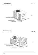
Page 3: ...c heater power wires Horizontal supply opening Horizontal return opening Fresh air 905 484 176 282 678 101 350 16 193 278 313 822 194 504 407 290 485 628 Horizontal supply opening Horizontal return op...

Page 4: ...panel Hole for electric heater power wires Horizontal supply opening Horizontal return opening Fresh air Units mm 20 Tons C O Units Hor Dow Units mm Electric heater control box access panel Hole for...

Page 5: ...viewed with a local engineer See the unit s nameplate for the absolute minimum clearance between the unit and any combustible surface s Rigging cables should have adequate capability to resist 3 times...

Page 6: ...e frame or roof curb Insulate any ductwork outside of the structure with at least 2 inches of insulation and then weatherproof There must be a weatherproof seal where the duct enters the structure Com...

Page 7: ...The first elbow in the ductwork leaving the unit should be no closer than 2 feet from the unit to minimize noise and resistance 5 4 Condensate drain piping 5 5 Ductwork Do not draw the canvas taut bet...

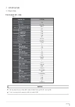
Page 8: ...a are based on the following conditions Evaporator Air Input Temperature 89 6 DB 73 4 WB Condenser Air Input Temperature 125 6 DB NOTES R410A 220V 3Ph 60Hz Electric heating STC each RNC each IPT each...

Page 9: ...ercurrent protection in sys B Overcurrent protection for indoor fan Comprehensive protection for outdoor fan Protection for Hi Lo pressure or exhaust temp in sys A Comprehensive protection in sys A Co...

Page 10: ...r inch Tube diameter in Type Drive type Type Drive type Motor RPM Motor RPM Length mm Width mm Heigth mm Refrigerant type Dimensions Compressor Cooling capacity net Btu h Heating capacity Btu h Rows Q...

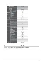
Page 11: ...type Motor RPM Motor RPM Length mm Width mm Heigth mm Refrigerant type Dimensions Compressor Cooling capacity net Btu h Heating capacity Btu h Net weight kg Rows Quantity Type Fins per inch Tube diam...

Page 12: ...type Motor RPM Motor RPM Length mm Width mm Heigth mm Refrigerant type Dimensions Compressor Cooling capacity net Btu h Heating capacity Btu h Net weight kg Rows Quantity Type Fins per inch Tube diam...

Page 13: ...type Motor RPM Motor RPM Length mm Width mm Heigth mm Refrigerant type Dimensions Compressor Cooling capacity net Btu h Heating capacity Btu h Net weight kg Rows Quantity Type Fins per inch Tube diam...

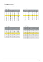
Page 14: ...wer KW Fan speed rpm 0 3250 1 83 1260 25 3149 1 78 1265 50 2996 1 70 1268 60 2941 1 66 1271 75 2886 1 63 1274 100 2782 1 58 1277 125 2664 1 53 1281 150 2540 1 47 1285 175 2411 1 41 1287 Static pressur...

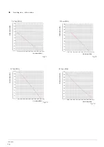
Page 15: ...00 150 175 200 225 250 125 0 25 Static pressure Pa Air volume CFM 2800 3000 3200 3400 3600 3800 4000 4200 4400 4600 50 75 100 150 175 200 225 250 125 Fig 15 T 0 25 50 75 100 150 175 200 225 250 125 St...

Page 16: ...75 T 7 5 Tons T 15 Tons Air flow CFM Static pressure Pa Brake power kW Fan speed rpm 0 20 10 11000 9800 9600 0 78 2 0 79 2 0 80 2 935 926 918 Tab 7 34 Air flow CFM Static pressure Pa Brake power kW Fa...

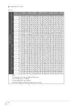
Page 17: ...3 78 4 75 3 76 5 77 9 80 4 76 1 78 6 80 3 82 5 84 4 86 1 87 8 89 6 86 3 88 0 89 8 91 6 87 8 89 6 91 3 93 2 89 1 90 9 92 7 94 6 51 0 65 0 79 2 86 3 53 7 66 2 85 0 90 3 56 3 73 3 90 6 92 3 58 8 77 2 90...

Page 18: ...90 4 92 2 94 0 95 2 97 1 99 0 101 0 93 4 95 3 97 2 99 1 101 2 103 2 105 3 107 4 110 3 112 5 114 8 117 1 112 9 115 2 117 5 119 8 114 6 116 9 119 2 121 6 116 3 118 6 121 0 123 4 67 6 86 4 105 9 115 6 7...

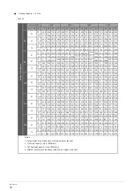
Page 19: ...4 5 138 6 181 4 176 0 183 9 179 0 198 5 140 1 171 0 164 1 175 9 170 6 193 1 138 9 166 1 159 4 163 6 163 6 183 3 136 5 159 7 154 9 157 3 152 6 176 2 131 3 169 9 146 1 191 0 111 2 198 3 74 9 160 8 140 1...

Page 20: ...8 240 5 149 5 191 6 185 9 200 8 180 9 226 9 141 0 249 3 241 8 254 2 238 1 270 2 183 1 239 7 230 1 242 9 236 4 262 3 185 1 225 9 219 1 232 4 209 1 255 1 183 5 219 4 212 8 216 1 216 1 242 1 180 4 207 0...

Page 21: ...h of the supply line from the main disconnect to the unit The line may be undersized for the length of the run Cooling shut down Place the system selector in the OFF position or reset thermostat at a...

Page 22: ...before cleaning and maintenance The unit shall be installed in accordance with national wiring regulations CAUTION Re install the air filter Condenser coil Unfiltered air circulates through the unit...

Reviews: