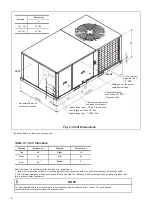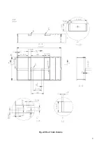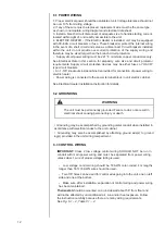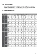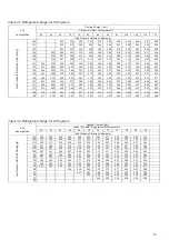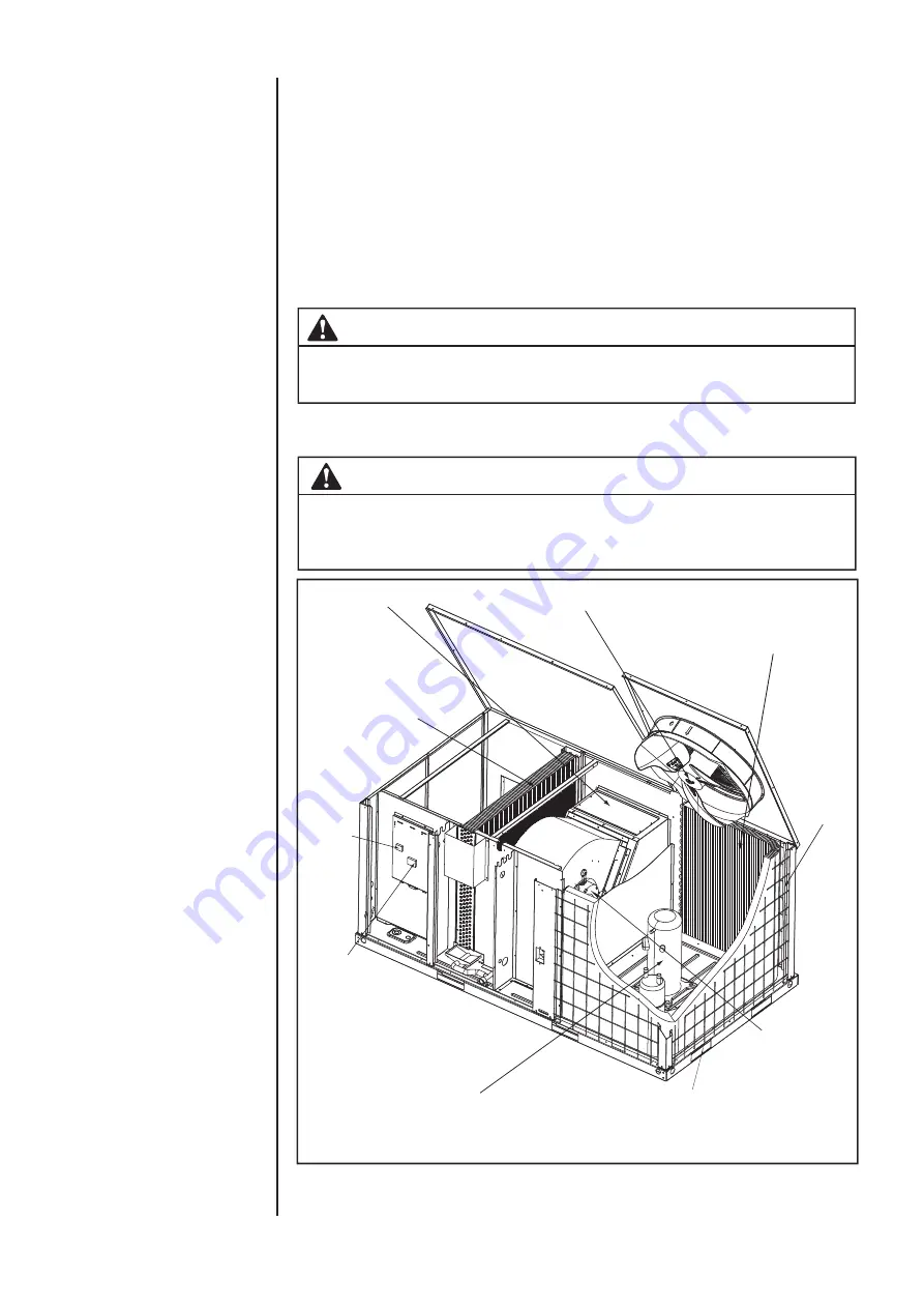
* The above figure for reference purpose only.
5
2.2 CLEARANCE
All units require certain clearance for proper operation and service. Refer to
Table 2-1
for the clearances required for construction, servicing and proper
unit operation.
2.3 RIGGING AND HANDING
Exercise care when moving the unit. Do not remove any packaging until the
unit is near the place of installation. Rig the unit by attaching chain or cable
slings to the lifting holes provided in the base rails. Spreader bars, whose
length exceeds the largest dimension across the unit, MUST be used across
the top of the unit.
CAUTION
Before lifting, make sure the unit weight is distributed equally on the rigging
cables so it will lift evenly.
Units may be moved or lifted with a forklift. Slotted openings in the base rails
are provided for this purpose.
All panels must be secured in place when the unit is lifted.
The condenser coils should be protected form rigging cable damage with
plywood or other suitable material.
CAUTION
Fig. 2-1 Component Location
Compressor
Highly efficient enhanced
copper tube / aluminum fin
indoor coil
Compressor
contactor
Low voltage
terminal block
Blower motor with
slide-out blower assembly
Decorative
protective coil
guard
Heavy gauge removable
base rails
Condenser fan motor
Electric heater assembly (optional)
Highly efficient enhanced copper
tube/Aluminum fin outdoor coil

