8
Warning
Warning
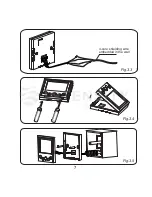
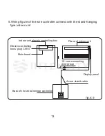
1.Insert the 4-core plug of the
connecting wires for the signal
receiving panel into the 4-core
socket of the signal receiving
panel. (
Fig.3.2
)
2.Connect the other terminal of
the connecting wires for the signal
receiving panel with the embed-
ded 4-core shielding wire, and
ensure the connection are reliable
and firm. (
Fig.3.2
)
3.Connect the led-out wire of the
wire controller with the embedded
4-core shielding wire, and ensure
the connection are reliable and
firm. (
Fig.3.3
)
4.Use a straight screwdriver to
insert into the catching groove in
the bottom of wire controller and
take down the bottom cover.
(
Fig.3.4
)
5.Adjust the length of two plastic
screw bars in the accessory to be
standard length from the electrical
box screw bar to the wall. Make
sure when install the screw bar to
the electrical box screw bar, make
it as flat as the wall.
6.Use cross head screws to fix the
wire controller bottom cover in the
electric control box through the
screw bar. Make sure the wire
controller bottom cover is on the
same level after installation, and
then install the wire controller back
to the bottom cover.
(Fig.3.5
)
Over fasten the screw will lead to
deformation of back cover and
fracture of liquid screen.
When install the bolts, please make
the screw bar height to be the same
with the wire controller and will not
out of shape.
When under installation, reserve
certain length of the connecting wire
for convenient to take down the wire
controller while during maintenance.
(
Fig.3.5)
Summary of Contents for KJR-86C-E
Page 4: ...INSTALLATION...
Page 10: ...7 Fig 3 5 Fig 3 4 Fig 3 3 4 core shielding wire embedded in the wall...
Page 17: ...OPERATION...


