background image

17 

IV.OPERATION    

    METHOD

SET TEMP DOWM

26°C SHORTCUT

Ś

FAN SPEED

Select fan speed

Quickly set the operation tempareture 
to 26°C

ś

Ŝ

ŝ

Ş

NO.

KEY

FUNCTION

SET TEMP UP

ON/OFF

Increase setting temperature

On/Off the unit

Decrease setting temperature

ON/OFF

Selecting mode:

1.When the unit is turned off, 
   press the ON/OFF button, the 
   unit will be turned on  and the 
   LCD screen of the wired remote 
   controller on.

2.When the unit is turned on,     
   press the ON/OFF button, the 
   unit will be turned off and the 

   LCD screen of the wired remote 
   controller off.

1.When the unit is turned on, 
   press the temperature adjusting 
   buttons “

Ÿ

” and  “

ź

” at the 

   same time for 3 seconds to 
   select the operation mode, each 
   press will switch the operation 
   mode as the following order:  
   COOL

ĺ

 HEAT

ĺ

COOL

Summary of Contents for KJR-86C-E

Page 1: ...WIRED REMOTE CONTROLLER MAN O KJR86C 0615 intensity mx INSTALLATION OWNER S MANUAL KJR 86C E Please read this manual carefully before operation and keep it for future reference...

Page 2: ...autions that should be brought to your attention during operation In order to ensure correct service of the wired controller please read this manual carefully before using the unit For convenience of...

Page 3: ...II OTHER PRECAUTIONS 4 III INSTALLATION PROCEDURE 6 IV WIRING FIGURE OF THE WIRED REMOTE CONTROLLER CON NECT WITH THE INDOOR UNIT 9 I MAIN PARAMETERS 15 II MAIN FUNCTIONS 15 III NAMES AND FUNCTIONS OF...

Page 4: ...INSTALLATION...

Page 5: ...rs and icons read the text body and observe the follow ing rules J Identifier description Identifier Meaning Means improper handling may lead to personal death or severe injury Means improper handling...

Page 6: ...rust the distributor or profes sionals to install the unit The installers must have the relevant know how Improper installation performed by the user without perm ission may cause fire electric shock...

Page 7: ...s are complete 1 2 3 4 5 1 2 2 1 1 No Name Qty Remarks Wired remote Controller Installation owner s manual II OTHER PRECAUTIONS Plastic screw bar For installing the wire controller on the electrical b...

Page 8: ...le must be connected stable to the ground or transmission may fail 4 Do not to attempt to extend the shield cable by cutting if it is necessary use Terminal Connection Block to connect 5 After finishi...

Page 9: ...le the length is decided by installation Indoor Unit Indoor Unit display panel Wired Remote Controller Principle diagram of wired remote controller Installation instruction figure 4 core shielding wir...

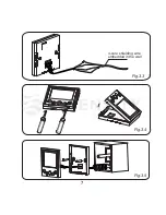
Page 10: ...7 Fig 3 5 Fig 3 4 Fig 3 3 4 core shielding wire embedded in the wall...

Page 11: ...h of two plastic screw bars in the accessory to be standard length from the electrical box screw bar to the wall Make sure when install the screw bar to the electrical box screw bar make it as flat as...

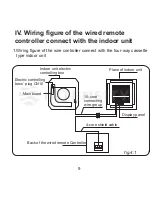
Page 12: ...of the wire controller connect with the four way cassette type indoor unit fig 4 1 A B C D Electric controlling boxs plug CN10 Main board 10 core connecting wire group 4 core shield cable Back of the...

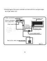
Page 13: ...courtyard style duct type indoor unit fig 4 2 A B C D Plane of indoor unit Indoor unit electric controlling box Electric controlling boxs plug CN10 Main board 10 core connecting wire group Display pan...

Page 14: ...oller connect with the high static pressure duct type indoor unit A B C D fig 4 3 Electric controlling boxs plug CN10 Main board Display panel Back of the wired remote controller Indoor unit electric...

Page 15: ...the wall hanging type indoor unit fig 4 4 A B C D Indoor unit electric controlling box Electric controlling boxs plug CN10 Main board 10 core connecting wire group Plane of indoor unit Display panel B...

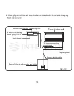
Page 16: ...the stand hanging type indoor unit fig 4 5 A B C D Indoor unit electric controlling box Electric controlling boxs plug CN10 Main board 10 core connecting wire group Plane of indoor unit Display panel...

Page 17: ...OPERATION...

Page 18: ...UNCTIONS MODEL Voltage input Ambient tempera ture range Ambient humidity range 9 5 a 5 a5 1 Set HEAT COOL operation mode 2 Set fan speed 3 Temperature setting range 17 C 30 C 4 Power down memory funct...

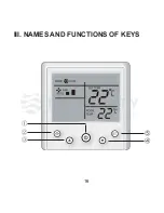
Page 19: ...16 III NAMES AND FUNCTIONS OF KEYS...

Page 20: ...it is turned off press the ON OFF button the unit will be turned on and the LCD screen of the wired remote controller on 2 When the unit is turned on press the ON OFF button the unit will be turned of...

Page 21: ...ck setting 1 When the unit is turned on you can press the 26 C shortcut key to quickly set the operation tempareture to 26 C Select the fan speed 1 When the unit is turned on press the FAN SPEED key t...

Reviews: