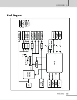
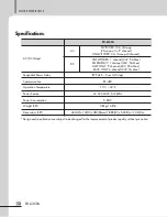


POWER DISTRIBUTOR
3
PD-6359A
Caution when assembling the RACKs
Caution when assembling the RACKs
- When using this device, exclusive model for our rack should be installed.
- If you decide to use the components made of other company, rated capacity should be verified, and confirm it
with an authorized dealer nearby.
- Rated capacity should be verified.
- Connecting it while power is off.
- Connect AC and DC powers based on the power of the device to be connected.
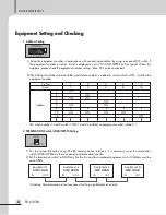
- When supplying the rack power, interlock AC OUTLET (Switched: 15A×3/Unswitched: 3A×1) and DC power
output (DC 24V, 5A) should be less than rated outputs.
Features
Package and accessory includes
Package and accessory includes
1. LAN cable x 1EA
2. Euro Terminal Block (5.08mm pitch) 3P x 1EA
3. User manual x 1EA
Features
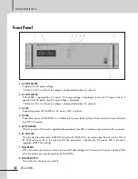
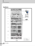
- RACK SYSTEM POWER CONTROL
It controls the power of the rack system.
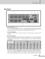
- AC OUTLET TERMINAL
It being consisted of UNSWITCHED 1 group and SWITCHED 3 group, and SWITCHED 3 group can output AC
power sequentially. (By using the BY PASS setting switch, the time of AC power output can be controlled
sequentially.)
- SUPPLY EMERGENCY POWER (DC 24V)
It can supply the battery power to the unswitched power output terminal, so it will be switched to emergency
power in case of black out to supply the DC power to the system.
- MONITORING OF VOLTAGE SUPPLYING STATUS
The status of service voltage can be monitored through Windows program.
- REMOTE CONTROL
Power can be on/off from Windows program, and it can be controlled through the contact of remote terminal
without PC.
- AC/DC VOLT METER
The status of service voltage can be monitored through front LED display consisting.
Summary of Contents for 5A0C828364DB-1
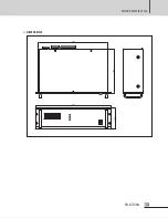
Page 15: ...POWER DISTRIBUTOR 13 PD 6359A DIMENSIONS 440 280 482 132...
Page 17: ...15 PD 6359A NOTE...
Page 18: ...16 PD 6359A NOTE...
Page 19: ...POWER DISTRIBUTOR 17 PD 6359A...