background image

Operation Manual

Reference Amplifier

R150 PLUS/300 PLUS/500 PLUS

* Rack mount products in the Western Hemisphere(North America, South America, and the Caribbean)

do not have handles installed due to customer preference.

Summary of Contents for Amplifier 300PLUS

Page 1: ...on Manual Reference Amplifier R150 PLUS 300 PLUS 500 PLUS Rack mount products in the Western Hemisphere North America South America and the Caribbean do not have handles installed due to customer pref...

Page 2: ...Instructions 3 Description 4 Features 4 Accessories 4 Front Panel 5 Rear Panel 6 Mounting in a Rack 7 Applications Stereo Installation 8 Bridge Mono Installation 9 Linked Installation 10 Connections 1...

Page 3: ...th a protective earthing connection It has heed to be easy to disconnect the device To disconnect the device from power separate AC input cable from inlet or unplug the AC Cord CAutION These servicing...

Page 4: ...evel input signal to either the balanced XLR or the balanced 1 4 TRS Tip Ring Sleeve connector marked INPUTS 4 Move the MODE selector to the desired position The Stereo position is the most common 5 C...

Page 5: ...o blades and a third grounding prong The wide blade or the third prong are provided for your safety If the provided plug does not fit into your outlet consult an electrician for replacement of the obs...

Page 6: ...o 8 load bridged mono R500 PLUS A 2U rack space 2 channel amplifier capable of 500W into 8 load bridged mono Features Features 4 stable per channel stereo 8 stable bridge mono 2U rack space Front pane...

Page 7: ...f a problem in the system when illuminated Reduce the volume and look for problems It is possible that the amplifier is too hot or the speaker impedance is too low This LED should not be illuminated d...

Page 8: ...nect the channel 2 input or any of the negative outputs 3 OUTPUT CONNECTORS Binding Posts and Locking speaker connectors are provided Bridged Mono operation requires a different method of connecting t...

Page 9: ...rear you should use special care to help ensure proper ventilation of the rack Here are suggestions to help keep the amplifiers properly ventilated 1 Leave a space of at least 10 cm 4 inches between t...

Page 10: ...8 R150 PLUS 300 PLUS 500 PLUS REFERENCE AMPLIFIER E n g l i s h Applications 1 Applications 1 STEREO INSTALLATION...

Page 11: ...9 R150 PLUS 300 PLUS 500 PLUS REFERENCE AMPLIFIER E n g l i s h Applications 2 Applications 2 BRIDGED MONO INSTALLATION...

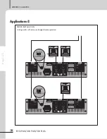
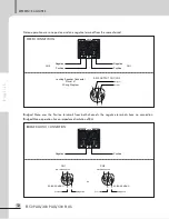
Page 12: ...10 R150 PLUS 300 PLUS 500 PLUS REFERENCE AMPLIFIER E n g l i s h Applications 3 Applications 3 LINKED INSTALLATION Linking works with stereo or bridged mono operation...

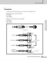
Page 13: ...gative Balanced 1 4 TRS connectors are wired as described Tip is Positive Ring is Negative Sleeve is Shield Insert Points Amp Line Input Headphones Unbalanced Input Output AUX Send Ring Ring Tip Tip S...

Page 14: ...has an impedance limitation of 8 Locking Speaker Connector Pin set 1 Wiring Diagram AMP OUTPUT CH1 CH2 1 1 2 2 Negative Positive or CH1 CH2 1 1 2 2 BRIDGED MONO Negative Negative Positive Positive BR...

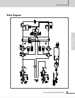
Page 15: ...13 R150 PLUS 300 PLUS 500 PLUS REFERENCE AMPLIFIER E n g l i s h Block Diagram Block Diagram...

Page 16: ...20kHz 0 5dB T H D 20Hz 20kHz half power 0 1 Channel Separation half power 8 70dB Residual Noise 80dB Signal to Noise Ratio 100dB Input Sensitivity rated power into 4 at 1kHz 0dBm Indicators Function...

Page 17: ...s List is available by contacting your warranty provider Variations and Options Variations and Options Variations Products supplied through legitimate sources are compatible with local AC power requir...

Page 18: ...Manual d Utilisation F r e n c h Amplificateur Professionnel R150 PLUS 300 PLUS 500 PLUS...

Page 19: ...21 Description 22 Caract ristiques 22 Accessoires 22 Face Avant 23 Face Arriere 24 Montage en Rack 25 Applications Configuration Mode St r o 26 Configuration Mode Mono Bridge 27 Configuration Mode ch...

Page 20: ...des pr cautions de bases incluant celle qui suivent Alimentation L appareil ne doit tre branch qu une source d alimentation correspondant au voltage sp cifi dans le manuel ou tel qu indiqu sur l appar...

Page 21: ...C blez une source dot e d un signal d entr e appropri soit aux connecteurs XLR sym triques soit aux connecteurs Jacks 6 35mm sym triques anneau masse pointe rep r s INPUTS 4 Adaptez le mode d sir l ai...

Page 22: ...ur est pourvu de 2 lames dont l une est plus grosse que l autre Une prise secteur est compos e de ces deux lames et d un troisi me concernant la masse Cette derni re repr sente la mise la terre donc c...

Page 23: ...ion et de mise sous tension Equerres de mise en rack pour une installation permanente dans une baie ou un rack au format 19 C ble secteur s par Accessoire Un c ble secteur s par est fourni avec cet ap...

Page 24: ...un probl me sur le syst me R duisez le volume et cherchez la cause du probl me Il est possible que l amplificateur soit trop chaud ou que l imp dance des haut parleurs soit trop basse Ces diodes ne do...

Page 25: ...nes positives des canaux 1 et 2 Ne rentrez aucun signal dans l entr e du canal 2 et ne branchez aucune charge sur les bornes n gatives de sortie 3 CONNECTEURS DE SORTIE Les sorties sont sur bornier do...

Page 26: ...vrez pr tez attention et vous assurez que le rack soit un minimum ventil Ci dessous quelques propositions pour garder vos amplificateurs proprement ventil s 1 Laissez un espace d au moins 10cm entre l...

Page 27: ...26 R150 PLUS 300 PLUS 500 PLUS AMPLIFICATEUR PROFESSIONNEL F r e n c h Applications 1 Applications 1 CONFIGURATION MODE ST R O...

Page 28: ...27 R150 PLUS 300 PLUS 500 PLUS AMPLIFICATEUR PROFESSIONNEL F r e n c h Applications 2 Applications 2 CONFIGURATION MODE MONO BRIDGE...

Page 29: ...28 R150 PLUS 300 PLUS 500 PLUS AMPLIFICATEUR PROFESSIONNEL F r e n c h Applications 3 Applications 3 CONFIGURATION MODE CHA NAGE Ce cas de figure peut tre utilis soit en mode st r o ou mono...

Page 30: ...s connecteurs XLR sont configur s comme suit Broche 1 Ground Masse Broche 2 Hot Point Chaud Broche 3 Cold Point Froid JACK SYMETRIQUE 6 35mm Les connecteurs au format jack 6 35mm sont configur s comme...

Page 31: ...ilisant une borne et une borne du m me canal Mode mono utilisant les 2 bornes des 2 canaux Les bornes n gatives ne sont pas utilis es ATTENTION En mode mono l imp dance est limit 8 Ohms OUTPUT CHANNEL...

Page 32: ...31 R150 PLUS 300 PLUS 500 PLUS AMPLIFICATEUR PROFESSIONNEL F r e n c h Synoptique Synoptique...

Page 33: ...T H D 0 05 150W 300W 460W 8 T H D 0 5 170W 330W 500W R ponse en Fr quences 20Hz 20kHz 0 5dB Taux de Distortion Harmonique 20Hz 20kHz 0 1 S paration de Canal Puissance 2 8 70dB Bruit R siduel 80dB Rap...

Page 34: ...mas Un sch ma lectronique de votre appareil peut tre fourni en vous adressant votre revendeur Liste des composants Une liste des composants lectroniques de votre appareil peut tre fournie en vous adr...

Page 35: ...mpany but rather a global company that is truly international in scope with factories and offices in Korea and China and sales and marketing operations located in Japan Europe and the U S A With more...

Reviews: