background image

SIGNAL PROCESSOR

18

CSP-4.8

Service

Service

Procedures

Take steps to insure the problem is not related to operator error or other products within the system. Information
provided in the troubleshooting portion of this manual may help with this process. Once it is certain that the
problem is related to the product contact your warranty provider as described in the warranty section of this
manual.

Schematic

A Schematic is available by contacting your warranty provider.

Parts List

A Parts List is available by contacting your warranty provider.

Variations and Options

Variations and Options

Variations

Products supplied through legitimate sources are compatible with local AC power requirements.

Options 

No optional items are available for this product.

Warranty

Warranty

Warranty terms and conditions vary by country and may not be the same for all products. Terms and conditions
of warranty for a given product may be determined first by locating the appropriate country which the product
was purchased in, then by locating the product type.

To obtain specific warranty information and available service locations contact Inter-M directly or the
authorized Inter-M Distributor for your specific country or region.

Summary of Contents for CSP-4.8

Page 1: ...but rather a global company that is truly international in scope with factories and offices in Korea and China and sales and marketing operations located in Japan Europe and the U S A With more than...

Page 2: ...Operation Manual Signal Processor CSP 4 8...

Page 3: ...device To disconnect the device from power separate AC input cable from inlet or unplug the AC Cord The socket outlet shall be installed near the equipment and shall be easily accessible CAUTION These...

Page 4: ...ents Unpacking 2 Installation Environment 2 Important Safety Instructions 2 Features 3 Front Panel 4 PROTEA NE Software 13 Troubleshooting 14 Block Diagram 15 Specifications 16 Dimensions 17 Service 1...

Page 5: ...her apparatus including amplifiers that produce heat 9 Do not defeat the safety purpose of the polarized or grounding type plug A polarized plug has two blades with one wider than the other A groundin...

Page 6: ...in Parametric EQ Filter Time delay Crossover Compressor Limiter Matrix routing 24 bit 48kHz delta sigma A D converters with 128x oversampling A backlit 2 x 20 character LCD displays channel and functi...

Page 7: ...ting preset configurations pre loaded into the unit which are simply starting points for common applications and all can be modified renamed and saved to suit the end user Please Note In addition to t...

Page 8: ...p to 6dB louder when combined 2 EQ The CSP 4 8 EQ section offers full parametric EQ as well as 1st and 2nd order shelving filters on inputs and outputs Each input channel has six selectable EQ filters...

Page 9: ...sweeping a narrow bandwidth filter through a problem feedback area with just a slight boost is a quick way to find the exact frequency causing trouble Once the offensive frequency has been found cut...

Page 10: ...ster so there exists the problem of same signals at the crossover points arriving at the cluster front at different times creating undesirable wave interaction and frequency cancellation The solution...

Page 11: ...crossover frequency and are used because they have a maximally flat passband and sharpest transition to the stopband When a Butterworth HPF and LPF of the same crossover frequency are summed the combi...

Page 12: ...nnatural while a very long attack time can miss some of the initial transient Similarly a very short release time can make the audio sound uneven while a very long release time can create pumping or b...

Page 13: ...ts When muted an input or output s red Mute LED is lit When an input or output is selected pressing the Mute button will toggle its mute function To quickly mute all outputs escape out to the top leve...

Page 14: ...D flashing at 0 indicates a signal level of 0dBu or 0 775Vrms To change this to a VU scale where 0VU 4dBu 1 228Vrms select the Ref option in the Util menu to VU Note Protea NE software for the CSP 4 8...

Page 15: ...fore clipping This unit is designed to clip at signal levels above 20dBu 7 75Vrms which places the noise floor lower than 90dBu The optimum input signal level which should be fed into the CSP 4 8 proc...

Page 16: ...ol a fixed physical sound system installation and can display any of the Inter M processors amplifiers and remotes used in that system The user can also place an assortment of isolated control objects...

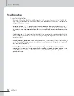
Page 17: ...low pass filter LPF Clip light stays on Is the input signal level too high Check to see that the nominal input level is 0dBu allowing 20dB of input headroom Are input or output gain settings too high...

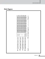
Page 18: ...Delay Gain EQ Select a Source for Each Output A B C D Any Combination Of Inputs HpfLpf EQ Delay Gain Limiter Mute 3 HpfLpf EQ Delay Gain Limiter Mute 2 HpfLpf EQ Delay Gain Limiter Mute 5 HpfLpf EQ De...

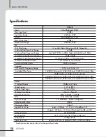
Page 19: ...9kHz Off Available Filter Types 12dB Oct Butterworth 12dB Oct Bessel 12dB Oct Linkwitz Riley 18dB Oct Bessel 18dB Oct Linkwitz Riley 24dB Oct Butterworth 24dB Oct Bessel 24dB Oct Linkwitz Riley 48dB...

Page 20: ...SIGNAL PROCESSOR 17 CSP 4 8 DIMENSIONS...

Page 21: ...e by contacting your warranty provider Variations and Options Variations and Options Variations Products supplied through legitimate sources are compatible with local AC power requirements Options No...

Page 22: ...13 DPA 430H 15 MA 106 NOTE...

Page 23: ...12 DPA 430H NOTE...

Page 24: ...3 DPA 430H...

Reviews: