background image

MIxIng AMplIfIer

4

pA-60A/120A/240A

Front Panel

Front Panel 

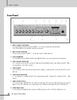
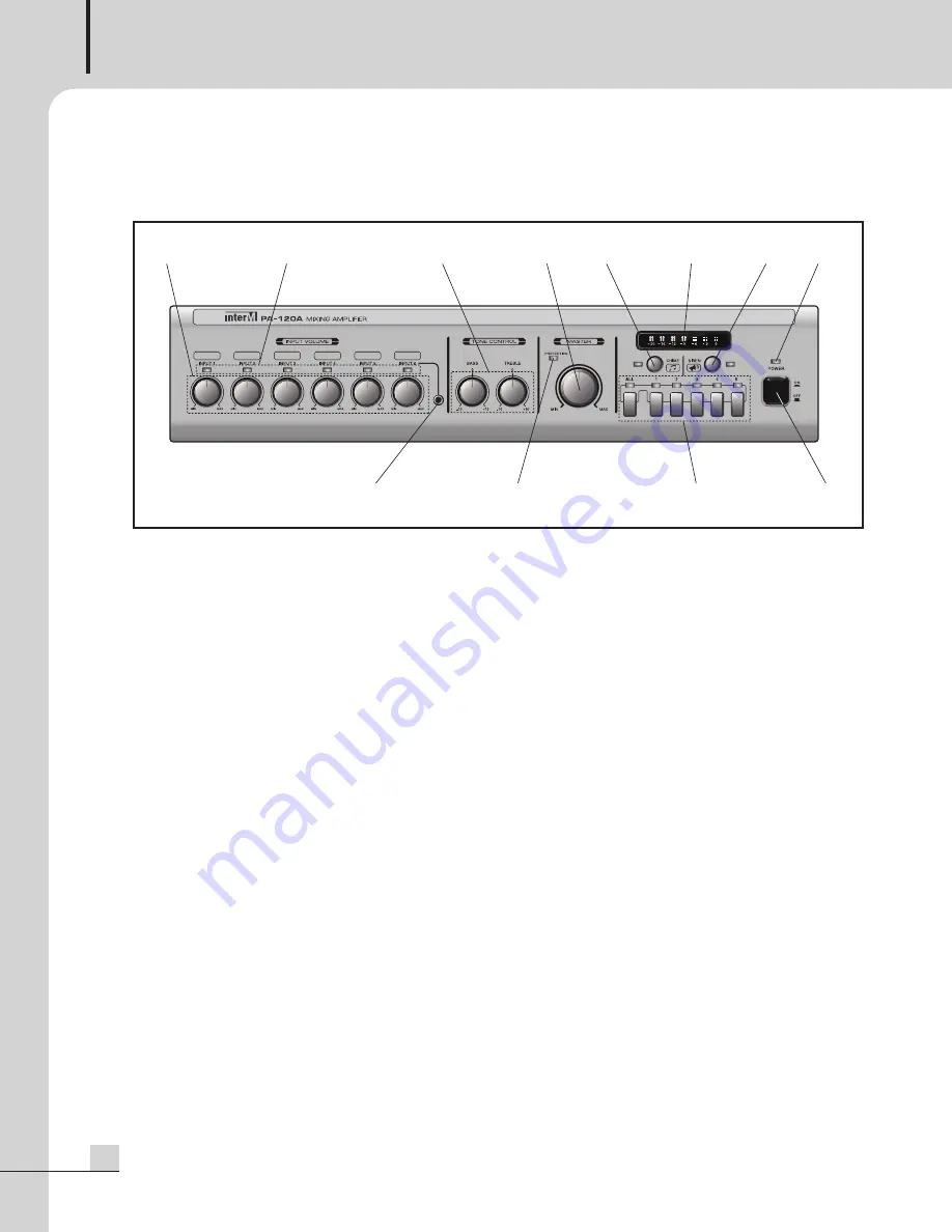
1.  InPUt VOlUME COntROllER

It is a controller to control the volume of InpUT 1 - 6. Use by controlling to desired volume.

Set the controllers of unused input terminals to minimum.

2. InPUt SIgnAl InDICAtOR

If there is an input signal to InpUT 1 - 6, due input signal indicator lights up.

3. tOnE COntROllER

It is a controller to control BASS (100Hz) and TreBle (10kHz). Users can control to their desired tones.

4. MAIn VOlUME COntROllER

It is a controller to control the volumes of whole signals controlled by each input volume controller. When
turning clockwise, the volume increases.

5. ChIME SWItCh

It is a switch to sound 4-note scale of chime. While chiming, a chime indicator on the left side of the switch
lights up.

6. OUtPUt lEVEl InDICAtOR

It  is  an  indicator  to  indicate  the  level  of  the  signal  being  printed.  Output  level  is  indicated  with  3  -  4dB
interval.

7. SIREn On/OFF SWItCh

It is a switch to turn On/Off the siren. When pressing once, the siren turns On and when pressing once
again, it turns Off. While the siren is operating, a siren indicator on the right side of the switch lights up.

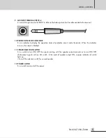
8. POWER InDICAtOR

It is an indicator to display the status of power. When the power switch is On, the indicator turns on.

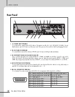
1

2

3

6

8

5

7

4

9

10

11

12

Summary of Contents for PA-120A

Page 1: ...Operation Manual Mixing Amplifier PA 60A 120A 240A ...

Page 2: ...e power supply cord plug from the AC receptacle The mains plug of the power supply cord shall remain readily accessible CAUTION These servicing instructions are for use by qualified service personnel only To reduce the risk of electric shock do not perform any servicing other than that contained in the operating instructions unless you are qualified to do so NOTE This equipment has been tested and...

Page 3: ...llation environment 2 Important Safety Instructions 2 Overview 3 Features 3 Package and accessory includes 3 Front Panel 4 Rear Panel 6 Application 10 Block Diagram 11 Specifications 13 Service procedures 15 Schematic 15 parts list 15 Variations and Options 15 Warranty 15 ...

Page 4: ...toves or other apparatus including amplifiers that produce heat 9 Do not defeat the safety purpose of the polarized or grounding type plug A polarized plug has two blades with one wider than the other A grounding type plug has two blades and a third grounding prong The wide blade or the third prong are provided for your safety If the provided plug does not fit into your outlet consult an electrici...

Page 5: ...Ω 4Ω pA A series are designed to allow the stable operation for voice play and BgM application and provide the ideal solution to various places like hospitals restaurants and schools Features Features ClASS D AMPlIFIERS hAVIng 60W 120W 240W OF OUtPUt hIgh Z 100V 70V AnD lOW Z 8Ω 4Ω MUltIPlE InPUtS thREE MICS lInES tWO lInES tWO StEREO lInE InPUtS tEl In AnD A FEAtURE FOR COntROllIng thE VOlUME OF ...

Page 6: ... controlled by each input volume controller When turning clockwise the volume increases 5 ChIME SWItCh It is a switch to sound 4 note scale of chime While chiming a chime indicator on the left side of the switch lights up 6 OUtPUt lEVEl InDICAtOR It is an indicator to indicate the level of the signal being printed Output level is indicated with 3 4dB interval 7 SIREn On OFF SWItCh It is a switch t...

Page 7: ...status of protection circuit inside the device When the indicator turns on the output is blocked 11 SPEAkER SElECtIOn SWItCh It is a switch to turn On Off the signals printing with five speaker output terminals or to turn On Off whole output signals with an All switch In the event of speaker output On a upper indicator of switch lights up Turn off the selection switch for unused speaker 12 POWER S...

Page 8: ...al to InpUT 1 CHIMe and SIren By using priority adjustment volume of InpUT 1 user can adjust the volume of InpUT 2 6 exT In 4 MIX OUtPUt MIX OUt tERMInAl It is an output terminal to connect when recording the sound printed from this device or using other amps in parallel It is a balanced type and pin arrangements are g 5 RM 05A COnnECtIOn tERMInAl It is a terminal to use by connecting our rM 05A p...

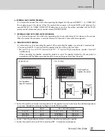
Page 9: ...connecting the speaker use not to be in overload state You can control Sp1 5 terminal with the speaker selection switch on the front side Be careful not to use 8 4Ω terminal and Sp1 5 terminal high impedance speaker terminal simultaneously When connecting the speaker connect the speaker to use to the speaker terminal on the rear panel in accordance with the following connection after removing the ...

Page 10: ...t tERMInAl OF InPUt 1 6 It is an input terminal of InpUT 1 6 InpUT 1 5 is configured with a balanced input circuit and InpUT 6 is configured with a rCA jack 1 Input terminal of InpUT 1 3 pHAnTOM switch When turning the switch On DC 15 V of phantom power is supplied to use with condenser mic input InpUT gAIn volume It is a volume to control gAIn of the input signal Do not use xlr jack and euro Term...

Page 11: ...e volume of InpUT 2 6 and exT In when the device is operated by the below status 1 When a signal is input to InpUT 1 or CHIMe and SIren is operated 2 When external MUTe switch is operated 3 When a signal is input to Tel In input terminal The broadcasting of InpUT 1 CHIMe and SIren signals are printed in priority rather than InpUT 2 6 exT In ...

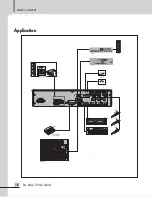
Page 12: ...MIxIng AMplIfIer 10 pA 60A 120A 240A Application Application AMP SPK MIXER ...

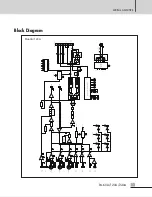
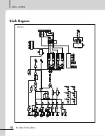
Page 13: ...ONE CONTROL SIG CHIME 0 100Hz 10kHz 10 10 LPF HPF MUTE BUFF SIREN CHIME SIREN PRESET 1 PRESET 2 PRESET 3 PRESET 4 PRESET 5 PRESET IN CHIME SWITCH SIREN SWITCH MUTE CONTROL 3 6 0 9 12 16 20 PROT LEVEL METER LED DRIVER PA 120 PA 60 50 10 AMP MIC LINE Vph PHANTOM POWER AMP PHANTOM POWER Vph AMP Vph PHANTOM POWER TEMP SENS PROTECTION CIRCUIT 0dBu MIX OUT CHIME SIREN 15V 15V B B AC IN POW ER SW ITCH PW...

Page 14: ...LINE Vph PHANTOM POWER AMP PHANTOM POWER Vph AMP Vph PHANTOM POWER TEMP SENS PROTECTION CIRCUIT 0dBu MIX OUT CHIME SIREN 20 0 dBu TEL IN INPUT 1 70 20dBu INPUT 2 70 20dBu INPUT 3 70 20dBu INPUT 5 INPUT 4 20dBu 20dBu 10dBu INPUT 6 RM 05 20dBu INPUT 6 50 10 MIC LINE 50 10 MIC LINE SIGNAL DETECTION TEL IN MUTE 0 MIX 0 MIX 10 GA 10 GA 0 BUFF 10 GA 10 GA 0 BUFF LIMMITER 10 GA 10 GA SPEAKER TERMIANL SP1...

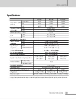
Page 15: ...d 3 5Φ pHOne JACK 10dBu 10kΩ UnBalanced Tel In input impedance 20 0dBu 10kΩ Balanced exT In input impedance 0dBu 20kΩ Balanced MIx OUT input impedance 0dBu 10kΩ Balanced Speaker output level output impedance 100V 167Ω 70V 82Ω 100V 84Ω 70V 41Ω 100V 42Ω 70V 21Ω TOne COnTrOl BASS 100Hz 10dB TreMBle 10KHz Operating Temperature 10 40 Operating power AC 220V 230V 240V 50 60 Hz power consumption 1 8W out...

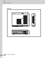
Page 16: ...MIxIng AMplIfIer 14 pA 60A 120A 240A DIMEnSIOnS 88 420 318 7 419 ...

Page 17: ...ilable by contacting your warranty provider Variations and Options Variations and Options Variations products supplied through legitimate sources are compatible with local AC power requirements Options no optional items are available for this product Warranty Warranty Warranty terms and conditions vary by country and may not be the same for all products Terms and conditions of warranty for a given...

Page 18: ...nOTe ...

Page 19: ......

Page 20: ...n company but rather a global company that is truly international in scope with factories and offices in Korea and China and sales and marketing operations located in Japan europe and the U S A With more than 850 employees around the globe Inter M is well poised for further growth and expansion Inter M Americas InC 5666 COrpOrATe AVe CYpreSS CA 90630 Tel 1 714 828 2200 fAx 1 714 828 2210 Home page...

Reviews: