D-0123672-H – 2022/05
Affinity Compact - Instructions for Use - US
Page
72
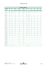
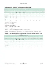
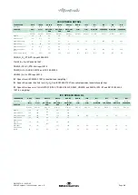
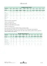
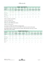
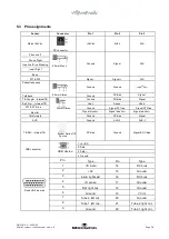
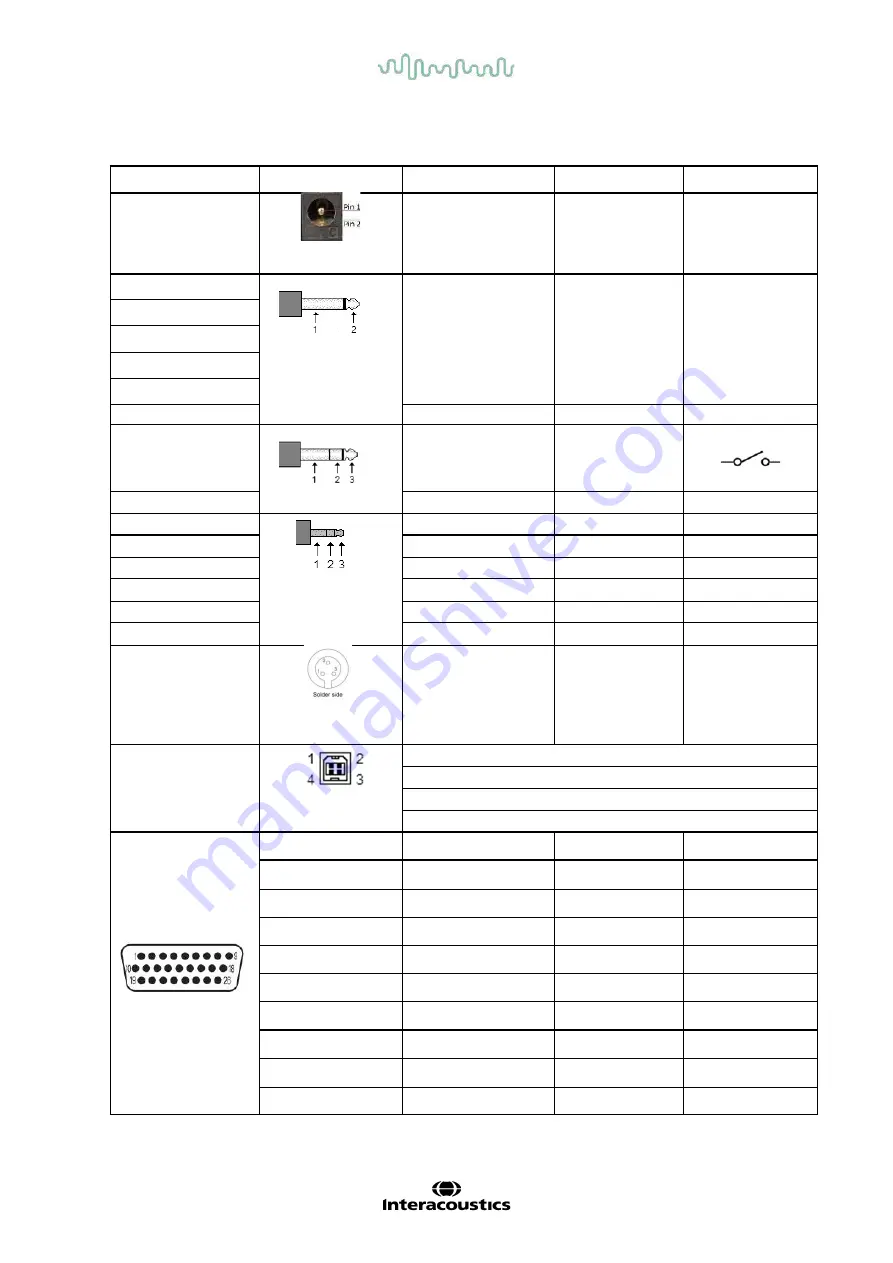
5.3 Pin assignments
Socket
Connector
Pin 1
Pin 2
Pin 3
Mains +24Vdc
+24Vdc
0Vdc
N/A
DC connector
Phone Left
6.3mm Mono
Ground
Signal
N/A
Phone Right
Insert Left / Ins. Masking
Insert Right
Bone
FF1 & FF2
Signal -
N/A
Patient response
6.3mm Stereo
Ground
Ground
Talk back
Ground
DC bias
Signal
TB Coupler - internal TB
3.5mm Stereo
Ground
DC bias
Signal
Batt. Sim. - Internal TB
Vbat-
Sense
Vbat+
FF1 & FF2 line
Ground
Signal FF1 line
Signal FF2 line
Monitor
Signal monitor -
Signal m
Signal m
Talk forward
Ground
DC bias
Signal
AUX
Ground
AUX-2
AUX-1
TB Ref – internal TB
Binder Series 719
3 poles
DC bias
Ground
Signal & DC bias
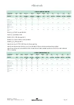
USB connector
USB device
1. +5 VDC
2. Data -
3. Data +
4. Ground
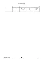
D sub HD 26 poles
Pin
Type
Pin
Type
1
I²C data
14
DC bias
2
+5V
15
Ground
3
Insitu right spkr
16
DC bias
4
ID sense
17
Ground
5
Ref right mic
18
Ground
6
Ground
19
I²C int
7
Tube 2 left mic
20
Ground
8
Tube 1 left mic
21
Tube 2 right mic
9
Ground
22
Tube 1 right mic

