background image

15

o

 Coil Roofing Nailer

Drives Coil Roofing Nails (¾" to 1¾" / 19 to 45mm)

Model No. CRN45-15

Item No. 65510

18

Interchange Brands  

Operator’s Manual

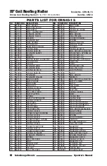
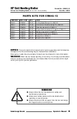
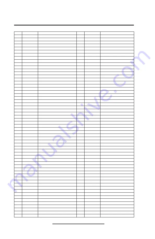
PARTS LIST FOR CRN45-15

NO. ORDER NO. DESCRIPTION

NO. ORDER NO. DESCRIPTION

1

610120

BOLT  M5X25

60

630110

SNAP RING

2

321790

SIDE PROTECTOR

61

420540

FILTER

3

421160

SIDE BAFFLE

62

510590

O-RING  43.7X2.65

4

321780

BOLT   (Loctite 243)

63

110410

END CAP

5

421150

EXHAUST COVER

64

610120

BOLT  M5X25

6

321590

EXHAUST FILTER

65

640010

ROLL PIN 2X8

7

410550

WASHER

66

420590

TRIGGER BRACKET

8

110400

CYLINDER CAP

67

620370

SPRING

9

620770

COM. SPRING

68

110190

ADJUST BUTTON

10

410540

PISTON STOP

69

320880

CONTACT PLATE

11

421140

HEAD VALVE PISTON

70

420580

TRIGGER

12

510910

O-RING  30X2

71

510580

O-RING  42.5X1.5

13

510920

O-RING  42X2.65

72

610100

BOLT  M5X20 (Loctite 243)

14

410530

CYLINDER SLEEVE

73

620790

CHECK PAWL  SPRING (A)

15

520270

GASKET

74

210550

CHECK PAWL (A)

16

410520

BUMPER

75

210540

CHECK PAWL (B)

17

321760

DRIVER BLADE (Loctite 262)

76

620780

CHECK PAWL SPRING (B)

18

421130

PISTON RING

77

322200

DOOR PIN

19

310360

PISTON

78

210530

DOOR

20

421120

CYLINDER RING

79

321900

CHECK PAWL PIN

21

520260

CYLINDER SEAL

80

640060

ROLL PIN  3X10

22

510930

O-RING  42.5X1.8

81

620840

LATCH SPRING

23

510940

O-RING  58X2.65

82

210590

LATCH

24

310350

CYLINDER

83

610060

BOLT  M5X10

25

421110

CYLINDER COLLAR

84

321890

WASHER

26

421100

GUARD COVER

85

610870

BOLT  M6X10 (Loctite 243)

27

421090

SAFETY GUIDE

86

210580

SAFETY LOWER

28

630090

SNAP RING

87

321880

SAFETY

29

321750

ADJUSTER

88

210570

NAIL GUIDE

30

510140

O-RING  5.15X1.8

89

620830

SPRING

31

421080

ADJUSTER DIAL

90

321870

STEP PIN

32

640020

ROLL PIN  2.5X10

91

510050

O-RING  2.8X1.8

33

321740

SAFETY UPPER

92

210560

NOSE

34

620670

SPRING

93

510280

O-RING  9X2

35

421070

SAFETY UPPER GUIDE

94

510400

O-RING  18X2

36

510950

O-RING  3.55X1.8

95

321860

FEED PISTON

37

210520

FEED PAWL

96

620820

FEED PISTON SPRING

38

420170

PIN CAP (A)

97

410560

FEED PISTON BUMPER

39

620760

FEED SPRING

98

321850

FEED PISTON CAP

40

321820

FEED PAWL PIN

99

610020

BOLT  M4X8 (Loctite 243)

41

510180

O-RING  5.8X1.9

100 321840

SCALE SHIELD

42

330010

TRIGGER VALVE BUSHING

101 421230

SCALE SLIDER

43

510210

O-RING  6.3X1.8

102 620810

SPRING

44

510240

O-RING  8.6X1.9

103 421220

SCALE BRACKET

45

620050

TRIGGER VALVE  SPRING

104 610340

HEX BOLT

46

320110

TRIGGER STEM

105 322180

SPRING HOLDER (A)

47

510030

O-RING  2.5X1.4

106 640160

ROLL PIN  3X25

48

420080

TRIGGER VALVE CAP

107 421210

MAGAZINE

49

510380

O-RING  16X1.8

108 421200

MAGAZINE POST

50

420090

TRIGGER VALVE CAGE

109 620800

MAGAZINE SPRING

51

510410

O-RING  18.3X2.65

110 421190

NAIL SUPPORT PLATE

52

640250

STRAIGHT PIN B3X15

111 421180

SPRING HOLDER (B)

53

620740

SPRING 

112 421170

MAGAZINE COVER

54

640180

ROLL PIN  3X30

113 510070

O-RING  3.15X1.5

55

110420

BODY

114 321830

MAGAZINE PIN

56

410460

HANDLE GRIP

115 323130

STRAIGHT PIN

57

321810

STEP PIN 

116 410880

STRAIGHT PIN CAP

58

420950

PIN CAP 

P1

D321761

DRIVER UNIT

59

640150

ROLL PIN  3X24

P2

T420091

TRIGGER VALVE

Summary of Contents for CRN45-15

Page 1: ...ol Carefully read through this OPERATOR S MANUAL to ensure efficient safe operation It is recommended that the MANUAL be kept readily available as an important refer ence when using this tool 15o Coil...

Page 2: ...4 Parts Identification 5 Accessories 5 Safety Information Safety Instructions 6 9 Employer s Responsibilities 9 Operating the Nailer Air Supply Connections Operating Pressure 10 11 Lubrication 11 Ope...

Page 3: ...could result in DEATH or SERIOUS INJURY Most accidents that result from the operation and maintenance of nailers are caused by the failure to observe basic safety rules or precautions An accident can...

Page 4: ...t and Fiberglass Shingles Fastening Lath Wire on Plywood Siding Installation and Wooden Box Assembly Nail Specifications WARNING Be sure to use only the genuine nails recommended for the CRN45 15 The...

Page 5: ...Exhaust Cover TOOL AIR FITTINGS This tool uses a minimum 1 4 N P T male plug The inside diameter should be 0 28 7mm or larger The fitting must be capable of discharging tool air pressure when disconn...

Page 6: ...ars from loud noise Wear head protection to protect your head from flying objects 3 KEEP FACE HANDS AND FEET AWAY FROM FIRING HEAD AT ALL TIMES Never place your face hands or feet near the firing head...

Page 7: ...ly and arrange for repairs by an authorized service center 16 BEFORE STARTING WORK CHECK THE FASTENING OPERATION SWITCHING DEVICE This nailer includes a fastening operation switching device Check the...

Page 8: ...o live wires 26 HOSES Air hoses should be professional grade and have a minimum of 150 psi working pressure Make sure that the hose is securely fastened If there is any damage to the hose replace it b...

Page 9: ...PARTS ACCESSORIES OR FASTENERS Unauthorized parts accessories or fasteners may void your warranty and can lead to tool malfunction and resulting injuries Only authorized service personnel should repa...

Page 10: ...sors for Process Industries Moisture or oil in the air compressor may accelerate wear and corrosion in the nailer Drain daily Connections 1 Fittings Install a female coupler to the hose The female cou...

Page 11: ...rating pressure is 150 psi Select the operating pressure within this range for the best fastener performance The nail length and thickness and the hardness of the wood are factors in determining what...

Page 12: ...erate 8 Hold the tool with contact arm away from work piece and pull the trigger The tool must not operate 9 Disconnect the air supply OPERATION Danger to the eyes exists due to the possibility of fly...

Page 13: ...ings To change setting pull up on the post and twist to the correct step The nail support should be adjusted correctly to the position indicated in inches and millimeters inside magazine 3 NAIL LOADIN...

Page 14: ...to the diameters and length of fastener and the hardness of work piece WARNING Always follow the tool manufacturer s safety and maintenance instructions Always wear safety glasses with side shields w...

Page 15: ...lubrication Apply air tool lubricant Nails jam in tool Bent nails Replace with new nails Broken or chipped driver Replace piston driver assembly bumper Wrong size nail Replace with correct type of na...

Page 16: ...2 Remove all nails 3 Remove the jammed nail with a slotted head screwdriver 4 In case of frequent jams contact an authorized service center A qualified person should perform repairs and maintenance P...

Page 17: ...ofing Nailer Drives Coil Roofing Nails to 1 19 to 45mm Model No CRN45 15 Item No 65510 17 Interchange Brands Operator s Manual PARTS DRAWING SCHEMATICS FOR CRN45 15 Parts Drawing Schematics Parts List...

Page 18: ...0 Loctite 243 27 421090 SAFETY GUIDE 86 210580 SAFETY LOWER 28 630090 SNAP RING 87 321880 SAFETY 29 321750 ADJUSTER 88 210570 NAIL GUIDE 30 510140 O RING 5 15X1 8 89 620830 SPRING 31 421080 ADJUSTER D...

Page 19: ...afety Kit for CRN45 15 98452 CRN45K8 Kit 8 Feeder Kit for CRN45 15 WARNING Always follow the tool manufacturer s safety and maintenance instructions Always wear safety glasses with side shields when o...

Page 20: ...his warranty 4 Labor charges maintenance or loss damage and repairs resulting from improper operation are not covered by this warranty GENERAL WARRANTY CONDITIONS This warranty will be honored only if...

Reviews: