11
©interCo GmbH, Eitorf, 11/2011 · BA AL stand 01 da · Ret til tekniske ændringer forbeholdes
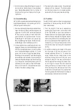
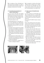
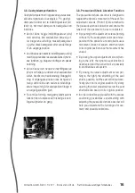
2 . Ved at betjene udløserhåndtaget en gang til
kan du løsne fastlåsningen af sædevippet
igen . Sædeskålssystemet kan nu flyttes til
lodret position igen ved hjælp af de to gas-
trykfjedre .
3.3. Skubbehåndtag
AKTIVLINE-understellets skubbehåndtag har to
indstillingsmuligheder, så skubning af AKTIV-
LINE kan gøres komfortabel:
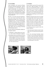
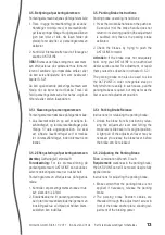
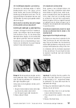
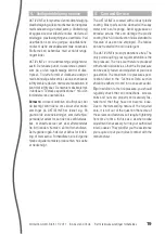
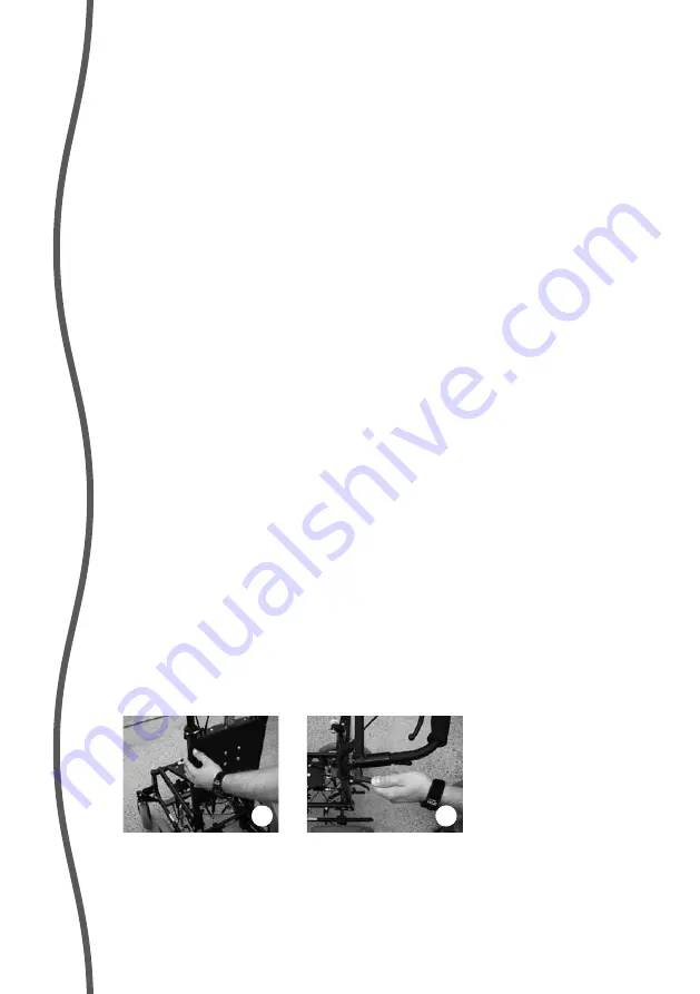
1 . Start med at indstille højden på skubbehånd-
taget ved først at åbne snaplukningerne på
rygrørene til AKTIVLINE, løsne låsefjederen
fra låsen ved at trykke let med tommelfin-
geren (billede 10) og flytte rørene til skub-
behåndtaget til den højde, der passer dig .
Når snaplukningerne lukkes, fastlåses skub-
behåndtaget i den indstillede position .
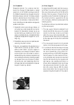
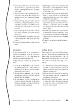
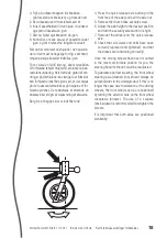
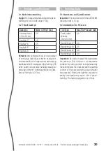
2 . Ud over højden kan du ved hjælp af de to ind-
byggede låseled på skubbehåndtaget også
indstille hældningsvinklen på den øverste
del af skubbehåndtaget (billede 11) . Dette
gøres ved at løsne begge fastspændings-
håndtag på låseleddene, indtil hældningen
kan indstilles uden besvær . Ved stramning af
fastspændingshåndtaget skal du altid sørge
for, at tapperne i låseleddet griber godt ind i
hinanden, så der opstår en fast forbindelse .
Ellers er der risiko for, at låseleddet smutter,
hvilket vil medføre unødig slitage .
10
11
2 . By pressing the release levers, the seat angle
adjuster will be released . The shell system
can then be returned to its original position,
assisted by the two gas-pressure springs .
3.3. Push Bar
The AKTIVLINE push bar offers two adjustment
possibilities to make pushing the AKTIVLINE
more comfortable:
1 . First, the height of the bar is adjusted by
pushing the tension lever on the back tube
of the AKTIVLINE to open the mechanism .
Release the lever by applying light pressure
with the thumb, whereby freeing the adjust-
ment spring (Photo 10) and allowing the push
bar to be positioned at the height most com-
fortable for you . The push bar position will be
locked into place by closing the adjustment
spring .
2 . In addition to varying the height of the push
bar, the angle of the bar can also be indi-
vidually adjusted (Photo 11) . To adjust the
angle, release the two clamp levers at the
structural tubing joints until they are open
enough to allow for the easy positioning of
the bar angle . When closing the clamp lever,
do not forget to ensure that the structural
tubing elements are nested firmly in each
other allowing a firm and secure hold . If the
connection is not sufficient, it is possible that
the tubing elements will slide apart leading to
unnecessary structural wear and tear .


