background image

Interflex Datensysteme GmbH   

18/23 

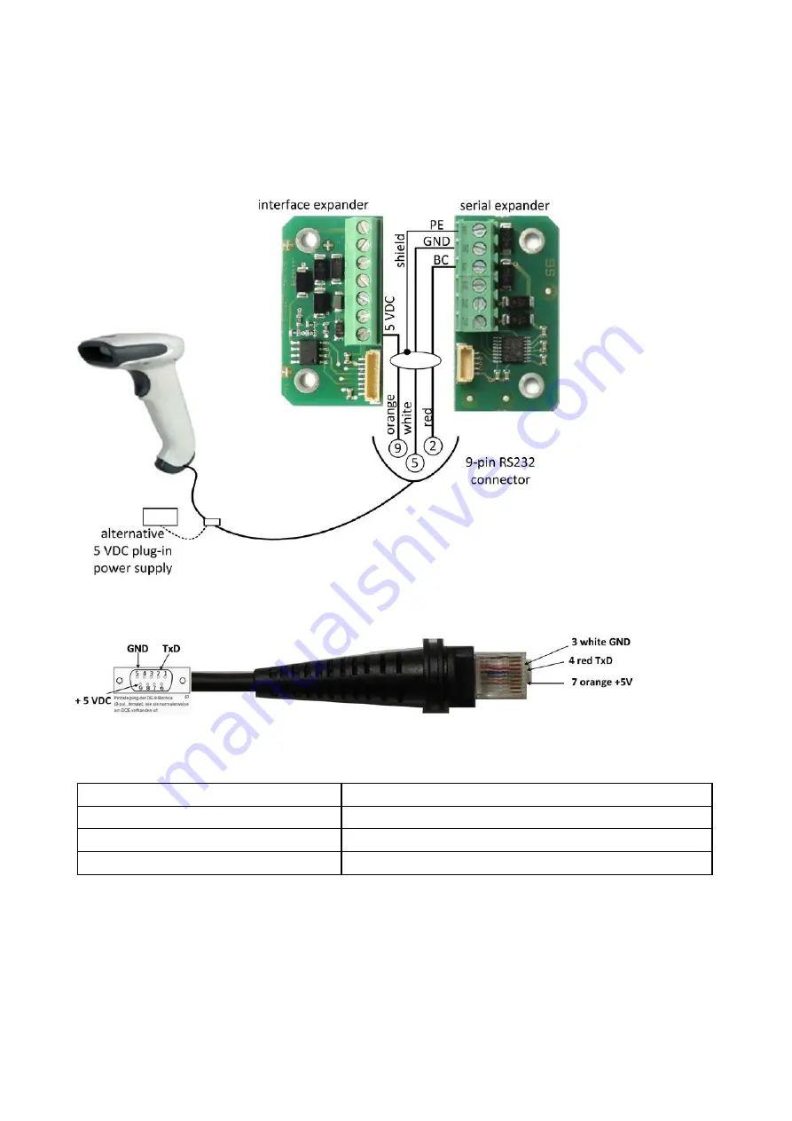
18.2.4 How to Connect a Barcode Reader 

Since a barcode reader requires an additional 5 VDC, this voltage can be supplied either by an Interface 
Expander (order number 75-5735-0003) or by an external power supply unit. The supply of power from an 
external power supply unit requires a cable (order number 90-10040) into which the power supply can be 
directly fed.    If the voltage is to be supplied by an Interface Expander, then the barcode reader is connected 
by the customer as follows: 


Note the following pin assignment when connecting the cable: 


18.2.5 Technical Specifications 

Supply voltage 

via the IP-57xx master terminal 

Voltage on the RS232 

- 12 V    / + 12 V   

Ambient temperature 

-25°C to +55°C 

Max. cable length of the RS232 interface 

15 m 


Summary of Contents for IF-57 Series

Page 1: ...amily can read data from state of the art RFID credentials Power is supplied via a low voltage power supply unit or PoE e g injector IF 5735 0xxx records time data such as e g IN OUT bookings or absen...

Page 2: ...ds To guarantee trouble free operation we recommend carrying out the electrical installation according to the principles of a TN S system which means using separate neutral and grounding conductors Se...

Page 3: ...sed functional grounding is connected to PE on the 3 pin terminal strip Check if there is functional grounding on the PoE device Ground PoE devices without functional grounding via existing soldering...

Page 4: ...Interflex Datensysteme GmbH 4 23 9 2 1 Power Supply via an External Transformer 9 2 2 Power Supply via PoE 9 2 3 RJ45 Patch Cable...

Page 5: ...ed Cable Type 1 230 VAC power supply to optional adapter 3 x NYM 1 5 mm 2 Low voltage cable for supplying power to IF 57xx J Y ST Y 4 x 2 x 0 6 mm or Flex JZ 3 x 0 75 mm 3 Ethernet patch cable to hub...

Page 6: ...the back panel of the housing only to an even surface If the cables are to be surface mounted a spacer is required black order no 75 5735 0001 or white order no 75 5735 0002 Recommended installation...

Page 7: ...erminal board are connected by a 14 pin connector The power supply as well as the connection to the data lines takes place via this connector 1 RJ45 female connector 2 Connector female end The female...

Page 8: ...LED lights up as soon as the terminal is detected by the network 5 Reset button The Reset button ends active processes and triggers a reboot restart 6 SW switch 2 The SW switch is used to set the sta...

Page 9: ...e found in the mounting instructions no 95 10304 which are included in the delivery of the kit A service connection is possible via 1 the service interface connected through a serial USB converter ord...

Page 10: ...signed to COM2 Using the device manager of your PC find out which COM port the IF USB serial adapter is using If your computer does not recognize the IF USB serial adapter you might have to reinstall...

Page 11: ...anged the password you have to login again for it to take effect 14 2 Configuring the Network Connection Network connections are configured with the command netpar x root poe 201 netpar x IP address 1...

Page 12: ...for the first time The touch screen has a layer that detects small electrical discharges such as those emitted by the human body Touch the screen with your fingertip The touch screen does not respond...

Page 13: ...0002 not for camera terminal Interface expander as I O expansion Order number 75 5735 0003 Serial expander for connection of a serial device e g a barcode reader Order number 75 5735 0004 18 1 Interfa...

Page 14: ...rminal Max cable length 100m PE Additional PE connection for an I O controller board COM and COM Interface to I O controller board Max cable length 100m 5VDC 5 VDC voltage supply for one I O controlle...

Page 15: ...ntroller board for an additional IF 800 terminal This I O controller board must be installed in a secured area Power is supplied via the power transformer 8 2 IF 57xx master terminal 6 Terminal strip...

Page 16: ...erial expander Back panel of the IF 57xx housing with a serial expander The serial expander is mounted to the back panel of the IF 57xx master terminal using 2 screws and 2 spacer sleeves Prevent shor...

Page 17: ...cation The corresponding interface parameters are also automatically defined with the selection of the device The barcode reader interface can be used to connect and operate various barcode readers su...

Page 18: ...rnal power supply unit requires a cable order number 90 10040 into which the power supply can be directly fed If the voltage is to be supplied by an Interface Expander then the barcode reader is conne...

Page 19: ...wn Screw the spacer along with the metal back panel to the wall Recommended installation height 1250 mm Fasten the PoE terminal board to the metal back panel of the IF 5735 Connect the wires to the Po...

Page 20: ...an appliance case behind the spacer This way you can variably adjust the cable length to facilitate inserting the RJ45 connector It would be beneficial if you could start the installation by connectin...

Page 21: ...Interflex Datensysteme GmbH 21 23 18 4 1 Installation This is how the IF 57xx master terminal is mounted onto the spacer 18 4 2 Mounting 1 IF 57xx 2 Bore holes...

Page 22: ...2mm Material Plastic Color Anthracite NCS7502B 75 5735 0005 or Silver RAL 240 70 05 75 5735 0006 19 Devices of the Series IF 57xx with WLAN or Camera Terminals of the series IF 57xx are also available...

Page 23: ...y performing source distribution Interflex offers to provide you with a medium customarily used for software interchange containing a complete machine readable copy of the source code of the programs...

Reviews: