background image

5

Intergraph does not recommend striping a 2-pack or logical drive across Smart cabinets and
SAF-TE cabinets.  For more information on striping, refer to the appropriate chapter in this
guide for the installed controller and the applicable software utility.  DAC960xx with
DACCF, DACADM, and DACMON utilities are found in Chapter 5.  MegaRAID with
MegaRAID BIOS setup and Power Console utilities are found in Chapter 6 and Chapter 7,
respectively.

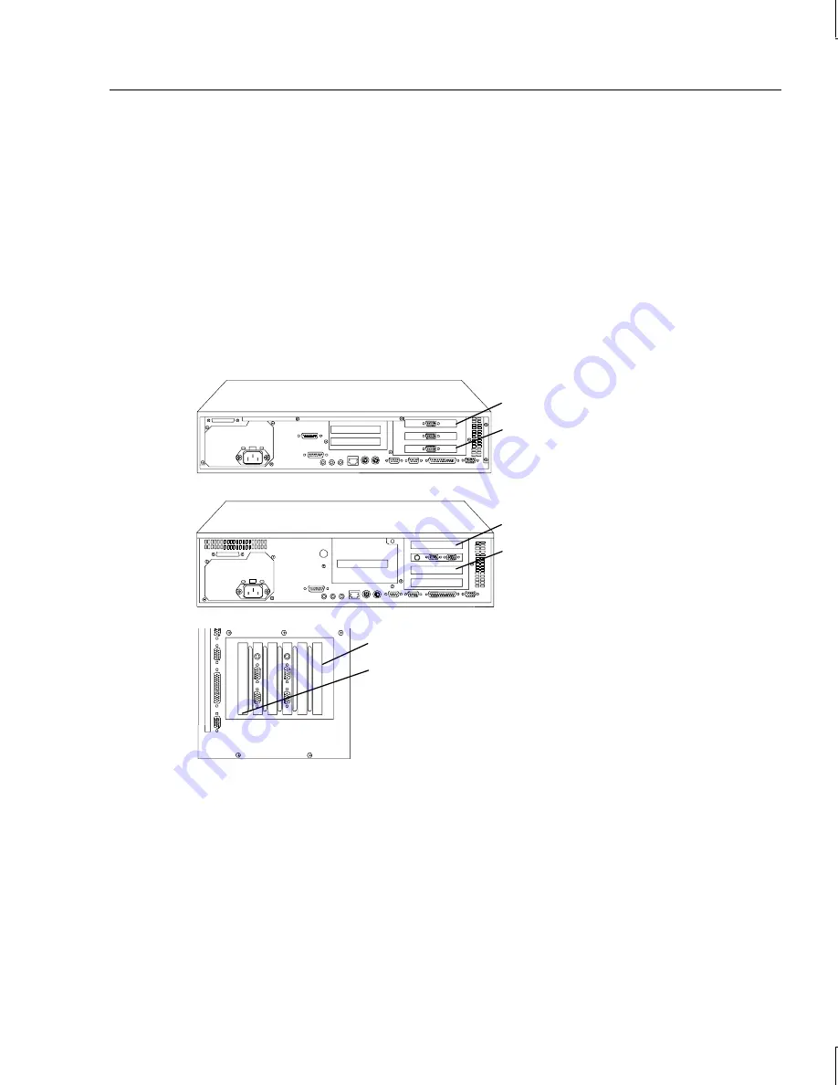
Identifying System PCI Slots  

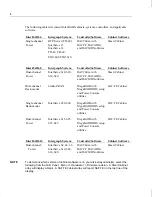
The following figures indicate PCI slot numbers for Intergraph’s system base units.

Using the Controller Software

Your system shipped with either a DAC960xx or a MegaRAID controller and the associated
software.  Be sure to determine which controller board is installed and use the proper
software when configuring.  Chapter 5 contains the software instructions for the DAC960P
and DAC960PD controllers, and Chapters 6 and 7 contains the software instructions for the
MegaRAID controller.

TD-xx, TD-xxx

DTP Server, InterServe 21
InterServe 6xx, TD-xx, TD-xxx,
TDZ-xx, TDZ-xxx

TD-x10, TDZ-x10

Slot 1

Slot 3

Slot 1

Slot 3

Slot 1

Slot 6

Summary of Contents for InterRAID-12

Page 1: ...InterRAID Hardware User s Guide January 1997 DHA018210 ...

Page 2: ...y software and its file formats and audio visual displays described herein all rights reserved may only be used pursuant to the applicable software license agreement contains confidential and proprietary information of Intergraph and or other third parties which is protected by copyright trade secret and trademark law and may not be provided or otherwise made available without prior written author...

Page 3: ...rence Regulations of the Canadian Department of Communications Warnings Changes or modifications made to the system that are not approved by the party responsible for compliance could void the user s authority to operate the equipment To reduce the risk of electrical shock do not attempt to open the equipment unless instructed Do not use a tool for purposes other than instructed There are no user ...

Page 4: ......

Page 5: ...et Monitoring 3 SAF TE Cabinet Monitoring 3 Door Lock 3 Describing Applicable Intergraph Systems 3 Identifying System PCI Slots 5 Using the Controller Software 5 Determining the RAID Controller 6 Connecting the Cabinet 6 2 Setting Up and Expanding InterRAID 6 7 Connecting InterRAID 6 to the System 7 Connecting Remaining Cabinets and Cables 8 Expanding the System 8 Unpacking 9 Setting Up Host 9 Ins...

Page 6: ...g the RAID Disk Drives 31 Powering On and Configuring the System 33 Important Operating Notices 33 Important Software Notices 34 5 Using DAC InterRAID Utilities 35 Updating the DAC960 Driver 35 DACADM and DACMON Utilities 36 Starting DACADM 37 DACADM Options 38 DACMON Overview 40 Starting DACMON 40 RAID BIOS Setup 40 Startup Sequence 41 Error Conditions While Checking the Drives 41 Overview of DAC...

Page 7: ...rmat Menu 85 Rebuild Menu 86 Check Consistency Menu 86 Select Adapter Menu 87 Disable BIOS Menu 87 Configuring Arrays and Logical Drives 87 Choosing the Configuration Method 88 Designating Drives as Hot Spares 89 Using Easy Configuration 90 Using New Configuration 93 Using View Add Configuration 97 Initializing Logical Drives 100 Formatting Physical Drives 101 Rebuilding Failed Disk Drives 103 Usi...

Page 8: ...5 Properties 126 Logical Drive Menu 126 Change Policy 128 Advanced Menu 128 Removing a Drive 133 Designating Drives as Hot Spares 134 Securing Power Console 134 Saving Configuration to Floppy 135 8 Servicing the Disk Array 137 Precautions 137 Replacing RAID Controllers 137 Replacing Disk Drives 139 Replacing Power Supplies 139 Replacing Cooling Fans 140 Replacing Cabinets 141 9 Identifying the RAI...

Page 9: ...nterRAID 6 153 InterRAID 8 154 InterRAID 12 155 B Troubleshooting 157 General 157 Error System fails to power on 157 Error InterRAID drive keeps going dead same physical drive each time 157 Error System hangs while loading operating system 158 Error System hangs when scanning devices 158 Error Installation aborted 158 Error No ROM Basic message displays 158 Error HDD blinking amber CHM blinking am...

Page 10: ...164 Microprocessor Failures 164 RAM Checksum Failure 165 SCSI Bus Access Failure 165 Hardware and Software Failures 166 InterRAID 8 Power Supply Failures 166 Disk Drive Rebuild and Disk Drive Failure 166 Windows NT Server Failure 167 Removable Media Drive Failure 167 Glossary 169 Index 177 Returning Equipment to Intergraph Returned Goods Authorization RGA Form Shipping Labels ...

Page 11: ...Chapter 4 Setting Up and Expanding InterRAID 12 describes setting up and expanding the InterRAID 12 cabinet u Chapter 5 Using DAC InterRAID Utilities describes how to install and use the Disk Array Controller Administrator DACADM and the Disk Array Controller Monitor DACMON utilities It describes using the RAID controller s Basic Input Output System BIOS and the Disk Array Controller Configuration...

Page 12: ...es on the keyboard such as D ALT or F3 names of files and directories You can type filenames and directory names in the dialog boxes or the command line in lowercase unless directed otherwise CTRL D Press a key while simultaneously pressing another key for example press CTRL and D simultaneously ALT SHIFT F Press keys sequentially for example press ALT then press SHIFT then press F Finding Operati...

Page 13: ...or an available class contact Intergraph Training Solutions at 1 800 240 3000 Getting Telephone Support If you experience problems with your Intergraph product or have questions about the information in this document you can contact Intergraph for help u In the United States call the Customer Response Center at 1 800 633 7248 between the hours of 7 00 a m and 7 00 p m Central Time Monday through F...

Page 14: ...nline Intergraph s World Wide Web server 3 When connected respond to the login request by keying in your user ID If you have not connected before key in new to create a user ID 4 Follow the menus to find what you need If you are new to computer bulletin boards the IBBS provides clear choices and plenty of online help A text file that explains IBBS commands and organization is available for you to ...

Page 15: ... have a Gopher program connect to Intergraph at gopher intergraph com u You can get information from Intergraph s email server at info intergraph com Put help in the body of the message the subject line is ignored to get information on such subjects as Intergraph s online services and where to get World Wide Web browsers u You can participate in the Intergraph Customer Forum ICF a bidirectional ga...

Page 16: ...rton contains the following items u InterRAID cabinet u Disk drive box with RAID disk drives u Key u Diskettes containing configuration and utility software u Accessory pack The accessory pack included with the cabinet contains the following items u InterRAID cabinet power cord u RAID SCSI cable u Four plastic feet u Eight cap head hex screws u Hex wrench u Disk drive labels u Drive Labeling instr...

Page 17: ... the RAID disk drives from the antistatic bags until you are ready to install them in the InterRAID cabinet Selecting a Location The InterRAID cabinets can be placed side by side or stacked Keep the following in mind when selecting a location u Allow six inches of space in front of the cabinet for the door to open u Allow at least a three inch clearance in back of the cabinet for air circulation u...

Page 18: ...toring SCSI Accessed Fault Tolerant Enclosure SAF TE is a new method to alert the user of abnormal system conditions SAF TE in addition to the Smart Cabinet monitoring functions listed above allows reporting to the system of the cooling fan revolutions per minute power supply voltages and temperature in degrees number of insertions per slot and number of powerup hours Door Lock The front door uses...

Page 19: ...5 DAC960xx with DACCF DACADM and DACMON utilities MegaRAID with MegaRAID BIOS setup and Power Console utilities MegaRAID with MegaRAID BIOS setup and Power Console utilities MegaRAID with MegaRAID BIOS setup and Power Console utilities Smart Cabinet SAF TE Cabinet SAF TE Cabinet SAF TE Cabinet InterRAID 12 Intergraph System Controller Software Cabinet Software Dual channel Tower InterServe 62 64 6...

Page 20: ...tifying System PCI Slots The following figures indicate PCI slot numbers for Intergraph s system base units Using the Controller Software Your system shipped with either a DAC960xx or a MegaRAID controller and the associated software Be sure to determine which controller board is installed and use the proper software when configuring Chapter 5 contains the software instructions for the DAC960P and...

Page 21: ...r 5 for either a DAC960P or DAC960PD controller or Chapter 6 for a MegaRAID controller Connecting the Cabinet Use the appropriate instructions in this guide when connecting the cabinet to the system base unit u For InterRAID 6 cabinets refer to Chapter 2 Setting Up and Expanding InterRAID 6 u For InterRAID 8 cabinets refer to Chapter 3 Setting Up and Expanding InterRAID 8 u For InterRAID 12 cabine...

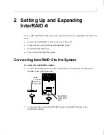
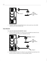
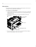
Page 22: ...dditional disk arrays u Install the RAID disk drives u Power on and configure the system Connecting InterRAID 6 to the System To connect the InterRAID 6 cabinet 1 Connect the RAID SCSI cable to the RAID SCSI port on the RAID controller board installed in the system base unit 2 Connect the other end of the RAID SCSI cable to the RAID SCSI port on the InterRAID 6 cabinet RAID Controller Board in Bas...

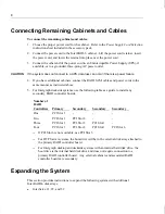
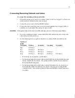
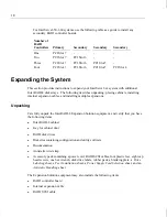
Page 23: ... as instructed above 5 For Intergraph deskside systems use the following table as a guide to install any secondary RAID controller boards Number of RAID Controllers Primary Secondary Secondary Secondary One PCI Slot 3 Two PCI Slot 3 PCI Slot 2 Three PCI Slot 3 PCI Slot 2 PCI Slot 1 Four PCI Slot 3 PCI Slot 2 PCI Slot 1 PCI Slot 6 If PCI Slot 6 is not available use PCI Slot 5 For DTP Server systems...

Page 24: ...ve Labeling sheet a Feet Installation sheet a Power Supply Cord Selection sheet and an Antistatic Handling sheet The Expansion Solution equipment may also include a RAID controller board CAUTION Do not remove the RAID disk drives from the antistatic bags until you are ready to install the drives in the cabinet Do not handle the RAID disk drives unless you connect an antistatic wrist strap to your ...

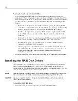
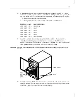
Page 25: ... are in the InterRAID disk array connected to the primary RAID controller For Intergraph desktop and deskside systems with an internal hard disk drive the internal hard disk drive is the boot disk drive and does not require connection to a primary RAID controller Any external disk arrays and associated RAID controllers are secondary 2 Route and connect the RAID SCSI cables and power cables to the ...

Page 26: ... Slot 1 Bottom 3 Install the boot disk drives in the primary InterRAID 6 cabinet To insert a drive extend the drive latching clips and slide the drive into the slot Push between the latching clips until the drive connects Close the drive latching clips until they snap into place locking the drive into the slot Refer to the following figure CAUTION Carefully insert the disk drives to avoid damaging...

Page 27: ...ve label information as appropriate Powering On and Configuring the System To prevent accidental power off or on the power switch is recessed and not accessible with the door closed and locked Before starting the system for the first time read the following important operating and software notices Important Operating Notices u Always power on the InterRAID 6 cabinet and wait for the audible beep b...

Page 28: ...Intergraph recommends connection to a UPS to guard against data loss u Intergraph configures the RAID controller board to RAID level 5 RAID controllers support RAID levels 0 1 5 6 0 1 and 7 The MegaRAID controller in addition to the other levels also supports RAID level 3 To power on and configure the system 1 Power on the InterRAID 6 cabinet and wait for the audible beep 2 Power on the system bas...

Page 29: ...ies or Chapter 6 Using MegaRAID BIOS and Chapter 7 Using Power Console 6 Use Disk Administrator in Windows NT to partition and format the disk space not used by the operating system When prompted to create a Signature File select Yes Refer to the Windows NT Server System Guide for information on using Disk Administrator ...

Page 30: ... rubber pads on the cabinet in the recessed area of each corner NOTE To connect the rack mount InterRAID 8 cabinet refer to the system s hardware documentation for the rack mounted system InterRAID 8 is available in two configurations single channel and dual channel The single channel cabinet has eight devices on one SCSI channel and the dual channel cabinet has four devices on each of two SCSI ch...

Page 31: ...Connect a RAID SCSI cable to the channel 0 port on the RAID controller in the base unit and to the channel 0 port on the InterRAID 8 cabinet 2 Connect a RAID SCSI cable to the channel 1 port on the RAID controller board in the base unit and to the channel 1 port on the InterRAID 8 cabinet RAID Controller Board in Base Unit RAID Controller Board in Base Unit Channel 0 Channel 0 Channel 1 ...

Page 32: ...he same manner as instructed above 5 Use the following table as a guide to install any secondary RAID controller boards Number of RAID Controllers Primary Secondary Secondary Secondary One PCI Slot 3 Two PCI Slot 3 PCI Slot 2 Three PCI Slot 3 PCI Slot 2 PCI Slot 1 Four PCI Slot 3 PCI Slot 2 PCI Slot 1 PCI Slot 6 If PCI Slot 6 is not available use PCI Slot 5 For Intergraph deskside systems with int...

Page 33: ... and installing multiple expansions Unpacking Carefully unpack the InterRAID 8 Expansion Solution equipment and verify that you have the following items u InterRAID 8 cabinet u Key for cabinet door u RAID disk drives u Diskettes containing configuration and utility software u Documentation u Antistatic wrist strap u Accessory pack containing a power cord RAID SCSI cables four plastic feet eight ca...

Page 34: ...ve locations You must install the drives in the same cabinets and slots from which you remove them 2 To rotate the Information Control Panel on the cabinet door open the cabinet door and remove the folded section of ribbon cable from the slit in the Mylar on the back of the door 3 Using a 5 16 inch nutdriver remove the hex nuts from the corners of the Information Control Panel 4 Rotate the Informa...

Page 35: ...nnel 2 connector of the secondary RAID controller board as shown in the following figure here the secondary RAID controller is installed in PCI slot 2 2 Route the internal expansion cable over the option board bracket as shown in the following figure 3 Using a quarter inch nutdriver remove the screw securing the ISA I O lock bracket as shown in the following figure Remove the lock bracket Internal...

Page 36: ...r internal expansion cable 8 Close the system s base unit as described in your system s documentation 9 Connect the disk array to the system as described in Connecting InterRAID 8 to the System Installing Multiple Expansions Once you understand how to expand a configuration by installing an additional RAID controller board and an internal expansion cable refer to the following figure to continue e...

Page 37: ...connector in the ISA I O slot Adding a third expansion to this InterRAID 8 configuration provides a maximum of four RAID controller boards supporting twelve disk arrays including the internal RAID subsystem The fourth RAID controller board will reside in either PCI slot 6 or 5 depending on which slot is available The third expansion will also use an available ISA I O slot and the RAID SCSI cable C...

Page 38: ... disk drives 1 Unlock the front panel door using the key for the InterRAID 8 cabinet 2 Remove the RAID disk drives from the carton labeled This box contains disk drives loaded with operating system software The first three drives ID 0 1 2 contain the operating system The following table shows the order in which to install the boot disk drives Disk Drive Label InterRAID 8 Slots ADP CHN ID 2 Slot 3 ...

Page 39: ...d number ADP X channel number CHN Y and SCSI ID number ID Z In the tables below Intergraph reserves SCSI ID 3 for the entire disk array and SCSI ID 7 for the RAID controller board In a single channel InterRAID 8 cabinet all eight RAID disk drives connect to a single channel Use the following table to label the drives Disk Drive Label InterRAID 8 Slots ADP X CHN 0 ID 9 Slot 8 top if deskside left h...

Page 40: ...e door closed and locked Before starting the system for the first time read the following important operating and software notices Important Operating Notices u Always power on the InterRAID 8 cabinet and wait for the audible beep before powering on the system base unit u If you turn off the power to the system base unit before completing the setup procedures you must reload the operating system O...

Page 41: ...troller board installed in the system For DAC960P and DAC960PD boards install the DACADM and DACMON utilities Refer to Chapter 5 Using DAC InterRAID Utilities For MegaRAID boards install the MegaRAID BIOS and Power Console utilities Refer to Chapter 6 Using MegaRAID BIOS and Chapter 7 Using Power Console WARNING After you configure the RAID disk drives it is very important that you backup the conf...

Page 42: ...InterRAID 12 to the System When setting up the InterRAID 12 cabinet in a vertical position first install the plastic feet on the cabinet according to the Feet Installation instruction sheet If setting up the cabinet horizontally install the rubber pads on the cabinet in the recessed area of each corner To connect the InterRAID 12 cabinet 1 Connect a RAID SCSI cable to the channel 0 port on the RAI...

Page 43: ... have additional cabinets connect the RAID SCSI cables and power cords in the same manner as instructed above 5 Use the following table as a guide to install any secondary RAID controller boards Number of RAID Controllers Primary Secondary Secondary Secondary One PCI Slot 3 Two PCI Slot 3 PCI Slot 2 Three PCI Slot 3 PCI Slot 2 PCI Slot 1 Four PCI Slot 3 PCI Slot 2 PCI Slot 1 PCI Slot 6 If PCI Slot...

Page 44: ... labels rubber pads a blanking plate a Drive Labeling sheet a Feet Installation sheet a Power Supply Cord Selection sheet and an Antistatic Handling sheet The Expansion Solution equipment may also include a RAID controller board CAUTION Do not remove the RAID disk drives from the antistatic bags until you are ready to install the drives in the cabinet Do not handle the RAID disk drives unless you ...

Page 45: ...binet 7 Place the bottom cabinet on its rubber pads on a flat hard surface not on carpet 8 For each additional InterRAID cabinet you want to stack repeat steps 2 through 6 and place the additional cabinet on top of the previous cabinet CAUTION You may stack up to four InterRAID cabinets in a single stack 9 If you removed RAID disk drives from existing InterRAID cabinets replace them Setting Up Hos...

Page 46: ...gh 3 5 inch form factor RAID disk drives Supported capacities include 1 GB 2 GB 4 GB and higher as the disk drives become available Contact an Intergraph sales representative for drive availability The left hand side of the disk drive label identifies the disk drive size NOTE Intergraph attaches a SCSI ID number to the disk drive label to identify each of the boot disk drives All other disk drives...

Page 47: ...e primary cabinet You can install them in any order as long as the slots are filled sequentially upward for example do not install drives in slots 5 and 7 leaving slot 6 empty If necessary fill in the label information for each RAID disk drive Refer to the Drive Labeling instruction sheet The disk drive label has blank spaces for you to apply the appropriate numbers to indicate the RAID controller...

Page 48: ...or closed and locked Before starting the system for the first time read the following important operating and software notices Important Operating Notices u Always power on the InterRAID 12 cabinet and wait for the audible beep before powering on the system base unit u If you turn off the power to the system base unit before completing the setup procedures you must reload the operating system Once...

Page 49: ...l the proper software utilities available for the RAID controller board installed in the system For DAC960P and DAC960PD boards install the DACADM and DACMON utilities Refer to Chapter 5 Using DAC InterRAID Utilities For MegaRAID boards install the MegaRAID BIOS and Power Console utilities Refer to Chapter 6 Using MegaRAID BIOS and Chapter 7 Using Power Console WARNING After you configure the RAID...

Page 50: ...troller Administrator DACADM and the Disk Array Controller Monitor DACMON NOTE If you need to load the new driver follow the applicable instructions in the following section for Windows NT 3 51 or Windows NT 4 00 The DAC960 driver resides on the same diskette containing DACCF Updating the DAC960 Driver The DAC960 driver provides an interface for administering the InterRAID disk array products Afte...

Page 51: ...T 4 00 1 Boot the system and log in as administrator 2 Open Control Panel 3 Select SCSI Adapters icon 4 Click the Drivers tab 5 Select the DAC960 driver 6 Click Remove to remove the old driver 7 Click the Drivers tab again 8 Click Add 9 Click Have Disk 10 Follow the instruction on the screen to install the updated driver 11 Remove the diskette containing the DAC960 driver from the disk drive 12 Re...

Page 52: ... Run command a srvccfg dacmon DAC960Monitor c winnt system32 dacmon exe In the above command it is assumed that the Windows NT system files have been copied in the directory named WINNT You can modify this command as appropriate Starting DACADM Before running DACADM under Windows NT 3 51 create an icon in the Administrative Tools program group To create an icon and start DACADM using Windows NT 3 ...

Page 53: ...ir own unique dialogs whereas the Device Selection dialog is common for all of the other entries The Device Selection dialog shows a matrix of the drives connected to the various channels of the selected RAID controller board The left most column of the corresponds to SCSI ID 0 The SCSI ID increments by one number for each column The letters STBY DEAD and ONLN indicate standby dead and online Duri...

Page 54: ...in two stages Idle the channel before removing the dead drive then idle the channel again before installing the new drive Make Standby Use this option to create a standby drive Select the dead DEAD drive box to make the dead drive a standby drive The RAID controller board will automatically try to start the drive If successful it will make the drive a standby drive NOTE Only drives that are not pa...

Page 55: ...dialog displays 3 Select Program Item The dialog displays 4 In the Description box type dacmon 5 In the Command Line box type dacmon 6 Select OK The dialog closes The next time the system reboots the minimized DACMON icon appears in the lower left corner of the display To view output from the Event Viewer 1 Under Administrative Tools select Event Viewer 2 At Log select Application The messages app...

Page 56: ... any of these messages displays call the Customer Response Center at 1 800 633 7248 for assistance Error Conditions While Checking the Drives If the firmware finds a valid DAC960 configuration but it does not match the SCSI drives currently installed one or more of the following messages display Unidentified device found at channel x Device identified for chn x tgt y found at chn x tgt y SCSI devi...

Page 57: ...m the first system drive on the primary RAID controller board Overview of DACCF To use DACCF you should be familiar with MS DOS and understand the basic terminology associated with RAID Refer to Chapter 10 and the glossary for basic information about RAID concepts and terminology The non volatile memory and flash EEPROM on the RAID controller board stores the DACCF configuration data When you rest...

Page 58: ...ilding WRO Rebuilding write only FMT Formatting SBY Standby drive Starting DACCF You must run DACCF from a diskette The boot sequence of the system must be A C If it is not refer to the system s hardware documentation for instructions to change the boot sequence To start the DACCF utility 1 Insert the DACCF diskette into the floppy disk drive and then restart the system 2 At the command prompt exe...

Page 59: ...is chapter 3 If the system contains more than one RAID controller board a menu similar to the following lists them according to the BIOS scan order MYLEX Disk Array Controller Configuration Utility Version X XX X XX XX 2 Channel 7 Target DAC960P 1 Firmware version x xx Select DAC960 DAC960P PCI 1 DAC960P PCI 2 DAC960P PCI 3 DAC960P PCI 4 Select DAC960 using cursor keys hit Enter ESC to Exit NOTE T...

Page 60: ...y Slot 6 6 Slot 5 7 NOTE The BIOS scans the secondary SCSI bus fifth and the primary SCSI bus eighth in the above scan order 4 Use the up and down arrow keys to highlight the RAID controller board to be configured and then press ENTER You can configure only one RAID controller board at a time NOTE If you use the default configurations outlined in this chapter the RAID controller board displayed as...

Page 61: ...highlighted option The following sections describe each option in detail 01 Automatic Configuration Use the Automatic Configuration option in the DACCF Main Menu only when three to eight disk drives of the same capacity are attached to the RAID controller the drives can be in different disk arrays This function aborts after displaying an error message if the drive capacities are different Automati...

Page 62: ...e resulting in lost data After the system saves the configuration a display similar to the following appears The display describes the configuration created MYLEX Disk Array Controller Configuration Utility Version X XX X XX XX 2 Channel 7 Target DAC960P 1 Firmware version x xx Automatic Configuration successfully done Make sure to INITIALIZE System drive 0 before exiting this utility Number of Sy...

Page 63: ...ler Configuration Utility Version X XX X XX XX 2 Channel 7 Target DAC960P 1 Firmware version x xx Choose this option to create arrange or cancel one or more packs and also to view information on the physical drives connected to the adapter New Configuration 1 Define Pack 2 Define System Drive Use Cursor keys for selection hit ENTER to select ESC to Exit NOTE Use New Configuration with caution or y...

Page 64: ...n Menu to low level format the drive On the lower right side of the display columns list the configured packs PAK number of drives in the packs DRVS and the size of the packs SIZE in megabytes Pack Definition contains four options you can select The following instructions describe how to use each option Create Pack allows you to create multiple packs containing multiple drives To create a pack 1 F...

Page 65: ...have to cancel the packs in reverse order from the way in which you created them 2 Press ENTER to cancel the highlighted pack or move the cursor to another pack and then press ENTER The pack is canceled and the Cancel Pack option highlights in the Pack Definition menu 3 Select another pack to cancel or choose another option in the Pack Definition menu Arrange Pack in the Pack Definition menu allow...

Page 66: ... highlights Refer to Define System Drive later in this section for more details Device Information in the Pack Definition menu displays information about a drive connected to the RAID controller The RAID controller can also display information for other devices such as CD ROM drives and tape drives To display device information 1 From the Pack Definition menu select Device Information The first di...

Page 67: ... Drvs column top left lists all the current arranged packs and their sizes The size specified for each pack is the sum of the capacity of the drives in the pack NOTE If the drives in a pack are not the same size then the size of the pack is a product of the number of drives in the pack and the smallest drive in the pack The Sys Drv column lower left lists all the created system drives their sizes ...

Page 68: ...each pack containing up to eight disk drives of any size as required 2 Divide each pack into system drives with each system drive less than or equal to 32 768 MB 3 Initialize the system drives If you require the entire amount of disk space to appear as a single system drive rather than as multiple 32 GB or smaller system drives you can combine the smaller drives into a logical volume using the Win...

Page 69: ...els Valid RAID levels are determined by the number of drives in the selected pack You can choose valid RAID levels only for the highlighted pack 2 Select a RAID level for the highlighted pack and then press ENTER The Enter Size window shows the maximum possible size for the system drive being defined NOTE The size you specify is the actual size of the system drive which includes the overhead for t...

Page 70: ... entirely discarded and the program returns to the DACCF Main Menu NOTE If you press ESC in the Save Configuration window the defined configuration remains intact and the program returns to the New Configuration menu You can continue later with the configuration process 7 Initialize all of the new system drives Refer to 05 Initialize System Drive in this chapter 8 Ensure the Array Encl MGMT I F op...

Page 71: ...or more additional packs Use Cursor keys for selection hit ENTER to select ESC to Exit View Update Configuration 1 Define Pack 2 Define System Drive Define Pack The existing packs can be canceled deleted or changed The newly added drives RDY and the existing standby SBY drives can be created into packs You can define a maximum of eight 8 physical drives per pack If you wish to cancel a pack and mo...

Page 72: ... the disk drive is online usable and CDR represents an installed CD ROM drive On the lower right side of the display columns lists the configured packs PAK number of drives in the packs DRVS and the size of the packs SIZE in megabytes Define System Drive Define System Drive of the View Update Configuration menu after additional packs have been created and arranged allows you to create additional s...

Page 73: ...or more information about the Array Encl MGMT I F option and other hardware parameters Intergraph recommends that you use the automatic rebuild feature rather than rebuild the replacement disks manually Systems using a redundant RAID level without standby drives in place pose a risk should one of the online drives suddenly fail The disk array will continue to function without interruption but the ...

Page 74: ...se it The process fills the drives with initialized data and synchronizes redundancy mirror or parity Errors can result if you fail to initialize a system drive For example the drive may not function properly fail to boot fail to install the operating system or fail the consistency check Also a change in the size of the system drives or packs requires that you initialize a system drive NOTE The in...

Page 75: ...configuration and return to the DACCF Main Menu 6 Ensure the Array Encl MGMT I F option is set to Enabled Refer to 09 Advanced Functions in this chapter for more information about the Array Encl MGMT I F option and other hardware parameters 06 Consistency Check Use the Consistency Check option in the DACCF Main Menu to verify data consistency on redundant system drives You should always execute a ...

Page 76: ...tion 8 Print Configuration Press any key to continue Tgt Channel Number ID 0 1 0 A 0 ONL 1 A 1 ONL 2 A 2 ONL 3 5 B 0 ONL 4 A 3 DED 6 B 1 ONL CDR Bad Block Table From the Tools menu if you select Bad Block Table BBT the View Bad Block Table menu displays and allows you to view the rebuild BBT and the write back BBT as follows View Bad Block Table View Rebuild BBT View Write Back BBT Select View Reb...

Page 77: ...ess the cursor keys to select a disk drive and then press ENTER A display similar to the following appears Channel 0 Target ID 1 Parity Errors 0 Soft Errors 0 Hard Errors 0 Misc Errors 0 3 Press ESC to return to the Tools menu The error counts will clear the next time you return to the View Bad Block Table menu Format Drive Use Format Drive in the Tools menu to low level format the physical drives...

Page 78: ... making a drive online 2 Press a key to dismiss the warning message The first drive available to the Make Online function highlights 3 Press the cursor keys to highlight a drive and then press ENTER A confirmation message displays Do you really want to make drive Online 4 Select YES The drive state changes to ONL 5 After selecting all the drives to be made online press ESC NOTE You can quickly mak...

Page 79: ...5 Type a filename for the configuration file Do not include directory paths Use a CFG extension as part of the filename to identify it as a configuration file The following message displays Existing File if any will be overwritten 6 Select YES and press ENTER 7 Remove the diskette from the floppy disk drive To restore a configuration 1 From the Tools menu select Backup Restore Conf 2 Select Restor...

Page 80: ...nfiguration The following message displays The existing config will be destroyed 2 Select YES to clear the configuration The disk drives in the disk array will not be accessible until you define a new configuration Print Configuration Use the Print Configuration option in the Tools menu to save a copy of the configuration in ASCII format to a floppy diskette or hard disk drive To save an ASCII ver...

Page 81: ... boards displays Refer to Starting DACCF earlier in this chapter for information about determining the difference between primary and secondary RAID controller boards 2 Select the RAID controller board to configure and then press ENTER Note that the banner at the top of the display shows the RAID controller board currently selected 3 DACCF scans the disk array to detect the drives connected to the...

Page 82: ...abled StorageWorks Fault MGMT TM Disabled NOTE The default hardware parameters are Battery Backup Disabled Array Enclosure Management I F AEMI Enabled StorageWorks Fault MGMTI F Disabled The InterRAID 6 InterRAID 8 and InterRAID 12 disk arrays do not support the Battery Backup option Intergraph recommends connection to a UPS to guard against data loss The Array Enclosure Management I F option shou...

Page 83: ...er activities The Stripe size K bytes option changes the way of accessing the information on the drives Stripe sizes of 8K 16K 32K and 64K are supported A higher stripe size results in a higher sequential throughput and a slightly reduced random throughput WARNING When you select a different stripe size all existing data on the drives will be lost Back up the drives before changing the stripe size...

Page 84: ...Bit is enabled Startup Parameters The options for the Startup Parameters Spin up option Number of devices per spin and Delay can be used to set up the way the disk drives spin initially However by default the InterRAID cabinet power supplies manage how the drives spin up so these options do not need changing The disk drives spin up one at a time with a four second delay between spin up If you chan...

Page 85: ...ng sections describe the errors Installation Aborted Errors If reporting an installation abort condition the following message displays Installation aborted The cause of this error includes a faulty SCSI cabling SCSI channel controller or improper power to the disk drives This error also occurs if you power off the InterRAID cabinet before the system To recover from an aborted installation 1 Press...

Page 86: ... the InterRAID cabinet and the system Controller Checksum Errors If a configuration checksum error is present DACCF displays the following message advising the user to reset the RAID to a default configuration The controller configuration table has a checksum error This may be due to corruption in the configuration tables stored in the controller s FLASH memory To overcome this problem the configu...

Page 87: ... Procedures This section provides a set of common procedures used to configure the disk arrays Enabling Automatic Rebuild The Array Encl MGMT I F option allows you to hot swap disk drives and automatically rebuild the replacement disk drive If Array Encl MGMT I F is enabled the RAID controller detects the replacement drive and automatically begins the rebuild process Array Encl MGMT I F is enabled...

Page 88: ...select the View Update Configuration option 7 Select the Define System Drive option then select the Toggle Write Policy option 8 Use the cursor keys to select a system drive then toggle the write policy option to Write Through or Write Back as desired 9 Press ESC twice to save the write policy setting 10 Select Yes to save the configuration 11 Exit DACCF remove the diskette and then restart the sy...

Page 89: ...bar shows the progress of the initialization After initialization is complete press any key to continue 14 From the DACCF Main Menu select Advanced Functions and then select Hardware Parameters 15 Toggle the Array Encl MGMT I F option to Enabled 16 Press ESC twice to save the setting 17 Select Yes to save the configuration 18 Exit DACCF remove the diskette and then restart the system 19 Under Wind...

Page 90: ...r each drive marked DED Then proceed to step 13 11 To backup or restore all drives at once select the Backup Restore Conf option of the Tools menu Press ENTER to confirm the warning message 12 Key in the filename for the configuration file Do not include directory paths If you used a CFG extension as part of the filename include the extension WARNING Do not key in the filename used for the ASCII v...

Page 91: ...76 14 Press ESC to exit the Tools menu 15 Press ESC to exit DACCF and then select YES at the confirmation window 16 Remove the DACCF diskette and restart the system ...

Page 92: ...ng u Startup Sequence u Management Menu Options u Exiting Setup u Setup menu tree u Configuring arrays and logical drives u Rebuilding failed disk drives u Using a pre loaded SCSI drive as is NOTE If you need to load the new driver follow the applicable instructions in the following section for Windows NT 3 51 or Windows NT 4 00 The MegaRAID driver resides on the same diskette containing the MegaR...

Page 93: ...t the driver is already present on the system 11 Select New then select Continue at the prompt to specify the path to the adapter files 12 At the SCSI Adapter Menu select Close 13 From the Options menu select Exit 14 Reboot the system To install the updated MegaRAID driver for use with Windows NT 4 00 1 Boot the system and log in as administrator 2 Open Control Panel 3 Select SCSI Adapters icon 4 ...

Page 94: ...that controller displays When you press CTRL M the following Management Menu displays Management Menu Configure Initialize Objects Format Rebuild Check Consistency Select Adapter Disable BIOS Management Menu Options The Management main menu options are as follows Option Description Configure Configures physical arrays and logical drives Initialize Initializes one or more logical drives Objects Ind...

Page 95: ... pages CONFIGURE Easy Configuration New Configuration View Add Configuration Clear Configuration INITIALIZE OBJECTS Adapter Clear Configuration FlexRAID PowerFail Flexible Dynamic Sizing Disk Spin up Timings Chip Set Type Cache FlushTimings Rebuild Rate AlarmControl Ultra SCSI Auto Rebuild Logical Drive Initialize CheckConsistency View UpdateParameters Physical Drive Rebuild Format MakeOnline Fail...

Page 96: ...ing configuration and or to specify additional arrays and logical drives View Add Configuration provides the same functions available in New Configuration Clear Configuration Select this option to erase the current configuration information from the MegaRAID controller non volatile memory Initialize Menu Choose Initialize from the Management menu to initialize one or more logical drives Initializi...

Page 97: ...ED The following table describes the Adapter menu options Option Description Clear Configuration Choose this option to erase the current configuration from the controller non volatile memory FlexRAID PowerFail Choose this option if you have battery backup installed Flexible Dynamic Sizing Choose this option if you plan on adding disk drives to the array and want to use the extra space without rebo...

Page 98: ...ive option from the Objects menu to select a logical drive and to perform the listed actions The following table describes the Logical Drives options Option Description Initialize Choose this option to initialize the selected logical drive This should be done for every logical drive you configure Check Consistency Choose this option to verify the correctness of the redundancy data in the selected ...

Page 99: ...ons listed in the table below The physical hard disk drives in the system are listed Move the cursor to the desired device and press ENTER to display the following The following table describes the Physical Drive options Option Description Rebuild Choose this option to rebuild the selected disk drive Format Choose this option to low level format the selected disk drive Make Online Choose this opti...

Page 100: ...tion on the controller for the lower eight bits This setting is required if the selected SCSI channel is terminated with 8 bit devices at both ends Terminate Wide Channel Choose this option to enable wide channel termination for the selected channel This is required if the MegaRAID controller is at one end of the SCSI bus for the selected channel Disable Termination Choose this option to disable t...

Page 101: ...Menu Choose Rebuild from the Management menu to rebuild one or more failed disk drives Check Consistency Menu Choose this option from the Management menu to verify the redundancy data in logical drives using RAID levels 1 3 or 5 When you choose Check Consistency the parameters of the existing logical drives on the current controller and a selection menu listing the logical drives by number appear ...

Page 102: ...s menu item allows you to enable or disable BIOS If you select yes to disable BIOS the menu item changes to Enable Configuring Arrays and Logical Drives You can configure physical arrays and logical drives with Setup using the following options u Easy Configuration u New Configuration u View Add Configuration Each configuration method requires a different level of user input The general flow of op...

Page 103: ...isturbed You can define a maximum of eight 8 logical drives per MegaRAID controller New Configuration In New Configuration you can modify the following logical drive parameters u RAID level u Cache write policy u Read policy u I O policy u Logical drive size u Spanning of arrays u Flexible Dynamic Sizing If you select New Configuration the existing configuration information on the selected control...

Page 104: ... arrays in Easy New or View Add Configuration mode u From the Objects Physical Drive menu select a physical drive and press ENTER Then select Make HotSpare When you choose any configuration option a list of all physical devices connected to the current controller displays as shown below Press the arrow keys to highlight a disk drive that has a READY indicator and press F4 to designate the drive as...

Page 105: ... hot key functions are as follows F2 Display the manufacturer data and error count for the highlighted drive F3 Display the logical drives that have been configured so far F4 Designate the highlighted drive as a hot spare 3 Press the arrow keys to highlight specific physical drives Press the spacebar to associate the highlighted physical drive with the current array The indicator for the selected ...

Page 106: ...l as any existing logical drives The column headings are as follows LD The logical drive number RAID The RAID level Size The logical drive size Stripes The number of stripes physical drives in the associated physical array StrpSz The stripe size Drive State The state of the logical drive 5 Set the RAID level for the logical drive Highlight RAID and press ENTER The available RAID levels for the cur...

Page 107: ...he logical drive You can set this parameter to Normal Read ahead or Adaptive Normal specifies that the controller does not use read ahead for the current logical drive Read ahead specifies that the controller uses read ahead for the current logical drive This is the default setting Adaptive specifies that the controller begins using read ahead if the two most recent disk accesses occurred in seque...

Page 108: ...as discussed later in this chapter Using New Configuration The New Configuration option allows you to associate logical drives with partial and or multiple physical arrays the latter is called spanning of arrays Choosing the New Configuration option erases the existing configuration information on the selected controller To use the spanning feature and keep the existing configuration use View Add ...

Page 109: ...ves to the current array as desired Try to use drives of the same capacity in a specific array If you use drives with different capacities in an array all the drives in the array is treated as if they have the capacity of the smallest drive in the array The number of physical drives in a specific array determines the RAID levels that can be implemented with the array RAID 0 requires one or more ph...

Page 110: ... logical drive Highlight Span from the bottom window of the logical drive configuration screen and press ENTER The choices are as follows CanSpan Array spanning is enabled for the current logical drive The logical drive can occupy space in more than one array NoSpan Array spanning is disabled for the current logical drive The logical drive can occupy space in only one array For two arrays to be sp...

Page 111: ...ray s being associated with the current logical drive thus accounting for the Span setting and for partially used array space For example if the previous logical drive used only a part of the space in an array the current logical drive size is set to the remaining space by default 9 Select Advanced from the bottom window of the logical drive configuration screen to set the remaining options NOTE F...

Page 112: ...follows F2 Display the manufacturer data and MegaRAID error count for the highlighted drive F3 Display the logical drives that have been configured F4 Designate the highlighted dri ve as a hot spare F10 Display the logical drive configuration screen 3 Press the arrow keys to highlight specific physical drives Press the spacebar to associate the highlighted physical drive with the current array The...

Page 113: ...l drives The logical drive configuration screen displays as shown below The window at the top of the screen shows the logical drive that is currently being configured as well as any existing logical drives The column headings are as follows LD The logical drive number RAID The RAID level Size The logical drive size Stripes The number of stripes physical drives in the associated physical array Strp...

Page 114: ...AID 10 RAID 30 or RAID 50 Logical Drives Configure RAID 10 by spanning two to eight contiguous RAID 1 logical drives The RAID 1 logical drives must have the same stripe size Configure RAID 30 by spanning two contiguous RAID 3 logical drives The RAID 3 logical drives must have the same stripe size Configure RAID 50 by spanning two contiguous RAID 5 logical drives The RAID 5 logical drives must have...

Page 115: ...zing Logical Drives You should initialize each new logical drive you configure You can initialize the logical drives in two ways u Batch Initialization u Individual Initialization To use batch initialization 1 Choose Initialize from the Management menu A list of the current logical drives displays as shown below 2 Press the arrow keys to highlight all drives Press the spacebar to select the highli...

Page 116: ...ys as a bar graph on the screen 4 When initialization completes press any key to return to the previous menu Formatting Physical Drives Choose the Format option from the Management menu to low level format one or more physical drives A physical drive can be formatted if it is not part of a configuration and is in a Ready state Since most SCSI drives are factory formatted do this step only if the d...

Page 117: ...ives press F10 and choose Yes at the confirmation prompt The indicators for the selected drives changes to FRMT number where number reflects the order of drive selection Formatting may take some time depending on the number of drives you have selected and the drive capacities 4 When formatting is complete press any key to continue Press ESC to return to the main menu To use individual formatting 1...

Page 118: ...e Description Automatic Rebuild MegaRAID automatically tries to use hot spares to rebuild failed disk drives Display the Objects menu Physical Drive option screen while a rebuild is in progress The drive indicator for the hot spare disk drive changes to REBLD A array number drive number indicating the disk drive to be replaced Manual Rebuild Manual rebuild is necessary if there are no hot spares w...

Page 119: ...nt menu A device selection window is displayed showing the devices connected to the current controller The failed drives have FAIL indicators 2 Press the arrow keys to highlight all drives to be rebuilt Press the spacebar to select the highlighted physical drive for rebuild 3 After selecting the physical drives press F10 and select Yes at the confirmation prompt The indicators for the selected dri...

Page 120: ...f the channels on the MegaRAID controller with proper termination and target ID settings 2 Boot the system and start Setup by pressing CTRL M 3 Choose Easy Configuration from the Configure menu 4 Press the cursor keys to highlight the pre loaded drive 5 Press the spacebar The pre loaded drive should now become an array element 6 Press ENTER You have now declared the pre loaded drive as a one disk ...

Page 121: ...106 ...

Page 122: ...MegaRAID Power Console utility is easy to install and use in the Windows NT environment An icon will be automatically created in the Power Console program group To install the Power Console utility for use with Windows NT 3 51 or 4 00 1 Boot the system and log in as administrator 2 Insert the diskette containing the MegaRAID Power Console utility into the floppy disk drive 3 For Windows NT 3 51 at...

Page 123: ... as hot spares u Securing Power Console u Saving configuration to floppy You can set up the logical drives as discussed in Chapter 6 using the MegaRAID BIOS Configuration utility If you have more than one MegaRAID controller in a host system be sure to configure at least one logical drive on every MegaRAID controller in the host system before you access the controllers from Power Console The numbe...

Page 124: ...og These buttons provide easy access to Power Console features You can remove the toolbox from the dialog by clicking on Hide Toolbox in the Adapter menu The buttons are described below Configuration Icons Display configuration click on this icon to display the current RAID system configuration For example ...

Page 125: ... this icon to allow you to configure the RAID subsystem Reset click on this icon to clear the RAID configuration on the currently selected controller A confirmation dialog will appear Click on OK in the confirmation dialog when it appears to reset the configuration Display log click here to display a list of MegaRAID activities Rebuild rate click on this icon to set the RAID rebuild drive rate ...

Page 126: ...drive to be rebuilt to this icon to rebuild the selected drive Initialize logical drive drag the logical drive icon that represents the drive to be initialized to this icon CAUTION If you reset your configuration by mistake you can recover it by re configuring the physical drives into the same array and logical drive structure they were in and by saving the configuration without initializing Logic...

Page 127: ...icons to group drives into RAID arrays The button on the logical drive icon indicates its status u Green indicates normal operation u Yellow indicates that the drive performance is degraded u Red indicates a failed drive With the cursor over a configured logical drive right click the mouse for a pull down menu of action options for that logical drive The channel icon consists of a stack of drive i...

Page 128: ...ndow Choose this option to view the progress of a disk rebuild diagnostic initialization parity check reconstruction or to view the performance monitor Help Choose this option to display information on Power Console The MegaRAID BIOS Configuration utility and the Power Console utility detect the presence of RAID controllers and assign controller numbers in two different ways In InterServe 650 660 ...

Page 129: ...ole counts the controllers incrementally from 0 to 3 but lists the controllers starting from PCI slot 6 or 5 and then from PCI slot 1 to PCI slot 3 The number assigned to the controller shifts according to the number of installed controllers The following table shows how both utilities list up to four installed RAID controllers PCI Slot BIOS Power Console 3 0 0 1 2 3 2 1 0 1 2 1 2 0 1 6 or 5 3 0 A...

Page 130: ... display an event log The events are stored in the file RAID log Diagnostics This option starts diagnostics on a physical drive that is in a Ready or Failed state Two types are available internal diagnostics and external diagnostics Enclosure Management Select this option to manage the drives in each physical RAID drive cabinet A picture of a RAID enclosure is displayed The actual real time state ...

Page 131: ...ons are available from the Adapter Menu Option Description Auto Configuration Select this option to automatically configure RAID arrays and logical drives This option generates the simplest RAID configuration possible with the current physical drives attached to the selected adapter Auto configuration 1 Attempts to gather physical drives of the same size into groups of five 2 Attempts to gather th...

Page 132: ...th this option each array you create is automatically treated as exactly one logical drive The Logical Drive Property dialog see below appears when you select this option Select the physical drives that will make up the logical drive Select the RAID type stripe size and write policy Reset Configuration Select this option to erase the current configuration information from the MegaRAID controller n...

Page 133: ...ust flush the contents of the cache memory to preserve data integrity View Log Select this option to display the MegaRAID event log The events are stored in the file RAID log Diagnostics Select this option to run either internal or external diagnostics on a physical drive that is in a Ready or Failed state The external diagnostics divide into two catagories sequential and random Enclosure Manageme...

Page 134: ... Click on any device displayed on the enclosure management dialog to display device information as shown Properties Select this option to display the adapter properties A dialog similar to the following appears ...

Page 135: ...logical drive icon and select Performance Monitor to display a graphic representation of drive performance A sample Performance Monitor dialog follows You can choose different logical drives the type of graph and the dialog arrangement from the Performance Monitor menus Object Identification Select this item to turn the object identification feature bubble help on or off This feature identifies ic...

Page 136: ...and Disable Alarm Control Enable Disable Alarm Control Choose this option to enable or disable the audible alarms and warnings Exit Choose this item to leave Power Console Physical Drv Menu The Power Console Physical Drv menu is as follows Rebuild Choose the Rebuild option from the Physical Drv menu to rebuild one or more failed disk drives ...

Page 137: ...Abort Rebuild Select Abort Rebuild to stop the rebuild process at any time The drive will revert to its original status before the rebuild began Format Formatting is not supported in Power Console It is recommended that you format drives using the MegaRAID BIOS Configuration Utility Diagnostics Select this option to run either internal or external diagnostics on a physical drive that is in a Ready...

Page 138: ...he Power Console Logical Drv Drive menu is as follows Create Choose the Create option to create arrays A dialog such as the following appears You can select the RAID type stripe size write policy read policy and cache policy ...

Page 139: ...at the appropriate drives are included in the array and click on OK You must also initialize these drives For channel information position the cursor on one of the SCSI channels and click on the right mouse button The following sample dialog displays Initialize Choose this option from the Logical Drv menu to initialize logical drives A dialog such as the following appears Choose the logical drives...

Page 140: ...l Drv menu to make sure that parity is correct for the selected drives A dialog such as the following appears Click on the drive to be checked D1 D8 and click on the Go button RAID levels 1 3 and 5 use an extra drive to store parity data blocks Parity is checked between these parity data blocks and the selected drives when you select this option ...

Page 141: ...use button on a logical drive in the Power Console menu you can change or expand any logical drive without halting system operations You can perform sophisticated RAID operations on preconfigured RAID logical drives u Change Policy u Advanced Menu To access the Logical Drive menu from the MegaRAID Power Console you must first click the right mouse button on a logical drive you want to change Then ...

Page 142: ...D Power Console dialog is available for you to use To delete a physical drive from a RAID logical drive just drag and drop a physical drive over it Other options also appear in the Advanced Menu pulldown after you select a logical drive and click the right mouse button ...

Page 143: ... dialog displays 3 Select the down arrow button under each policy Write Read or Cache to display a list of the available policies for this array Click on a new policy to select it 4 Select OK when you have completed all policy changes Advanced Menu The Advanced Menu from the Logical Drive pulldown menu allows you to change a configuration and to add a drive to an existing configuation You can defi...

Page 144: ... or RAID 5 Optimal RAID 0 Delete a drive or add drives RAID 3 or RAID 5 RAID 0 Optimal If a drive fails you can configure an Optimal RAID 0 system RAID 1 Optimal RAID 3 or RAID 5 Optimal Add drives RAID 1 Optimal RAID 0 Add drives or delete a drive RAID 1 Degraded RAID 0 If a drive fails you can configure an Optimal RAID 0 system RAID 0 RAID 3 or RAID 5 Optimal Add drives RAID 0 RAID 1 Optimal Add...

Page 145: ... Select Apply The Reconstructing dialog displays as follows 5 Click on the Info button of the Reconstructing dialog to display detailed information about the reconstruction operation being performed as shown ...

Page 146: ... or more physical drives u An Optimal RAID 1 logical drive can be converted to an Optimal RAID 0 RAID 3 or RAID 5 logical drive NOTE You can also convert between RAID 3 and RAID 5 by adding additional physical drives to the logical drive CAUTION The state of the physical drive to be added must be Ready The state of the RAID subsystem being modified must be Optimal To add a drive 1 From MegaRAID Po...

Page 147: ...e left button a check appears on the drive Select Apply The Reconstructing dialog displays as follows 4 Click on the Info button of the Reconstructing dialog to display detailed information as shown below about the reconstruction operation being performed ...

Page 148: ...xible Dynamic Sizing is enabled Removing a Drive You can change the configuration of any logical drive by removing a physical drive from the configured logical drive To remove a physical drive from a logical drive 1 Drag the physical drive icon from the MegaRAID Power Console to the trash can The Change RAID Level dialog displays ...

Page 149: ...ain menu click on the drive icon of the drive to be made the hot spare Select Tools from the menu Select Make Hotspare from the Tools submenu as shown The drive to be made a hot spare must have a the same or a greater capacity than the other drives in the RAID array When you select the icon for a SCSI device from the SCSI channels display in the middle of the above dialog the drive type and the ca...

Page 150: ... to save a new configuration to a diskette back up or to restore a configuration that is lost Always back up the configuration file for every InterRAID cabinet connected to the system To back up a configuration to floppy 1 Ensure the boot sequence for the system is A C 2 Insert the bootable MegaRAID diskette containing confmgr exe into the floppy disk drive 3 Restart the system Key in confmgr at t...

Page 151: ...ation file Restoring any other file will overwrite the binary code for setting the registers causing damage to the RAID controller board The board must be replaced CAUTION The restored configuration file must match the hardware configuration MegaRAID assumes the number of physical drives installed in the InterRAID cabinet is the same as the number of drives configured in the configuration file The...

Page 152: ...t to discharge any accumulated static charge u Avoid servicing the system in areas known to have electrostatic problems such as on rugs and carpets u Handle all printed circuit boards as little as possible and by the edges only Leave the boards in their protective packaging until you install them u Do not drop jar or bump the disk drives Handle all disk drives by the edges and avoid touching conne...

Page 153: ...e base unit and servicing any parts carefully read the Precautions section of this chapter If you do not heed these initial precautions carefully your system or replacement parts could be damaged and your warranty voided To replace or add a RAID controller board 1 Open the system s base unit and remove the RAID controller board Refer to your system s documentation for instructions on opening the b...

Page 154: ...label on the failed disk drive Remove the matching numbers from the label sheet and affix them to the front of the new disk drive 3 Extend the drive latching clips to disengage the failed drive from the disk array Then slide the disk drive out of the cabinet 4 Install the new disk drive by extending the drive latching clips and sliding the disk drive into the drive slot Place your thumb on the dri...

Page 155: ...rRAID 12 have hot swap cooling fans Do not attempt to replace the cooling fans in an InterRAID 6 If a cooling fan fails in the InterRAID 6 return the unit to Intergraph You do not have to power off the InterRAID 8 or InterRAID 12 to replace the cooling fans To replace an InterRAID 8 or InterRAID 12 cooling fan 1 Locate the failed cooling fan at the back of the cabinet The cooling fan will be stopp...

Page 156: ... The drives are labeled with an ID number 3 Place the new cabinet adjacent to the old cabinet 4 Shutdown and power off the system base unit then power off the cabinet to be replaced 5 Disconnect the AC power cord and RAID SCSI cable s from the old disk array 6 Connect the AC power cord and RAID SCSI cable s to the new cabinet 7 Remove the disk drives from the old cabinet and install them into the ...

Page 157: ...142 ...

Page 158: ...AC960P has two independent RAID SCSI bus channels 0 and 1 each using a separate 53C720 SCSI controller This allows the system to read or write data on several disk drives simultaneously The DAC960P RAID controller board is shown in the following figure Channel 1 is the default internal RAID SCSI connector CAUTION Ensure jumpers are installed as shown or erratic operation will occur SCSI Controller...

Page 159: ...al disk drives simultaneously The DAC960PD RAID controller board is shown in the following figure Channel 2 is the default internal RAID SCSI connector CAUTION Ensure jumpers are installed as shown or erratic operation will occur Channel 0 Flash EEPROM SCSI Controllers 53C720 i960 RISC Processor Channel 0 External Channel 1 Channel 2 Internal Cache Memory Channel 1 External JP5 JP6 JP4 ...

Page 160: ...llowing figure Channel 2 is the default internal RAID SCSI connector CAUTION Ensure jumpers are installed as shown or erratic operation will occur Features The RAID controller has the following features u PCI Bus Interface u AT Compatible BIOS u RAID Controller Firmware u RAID SCSI Bus Channel 1 External Flash EEPROM Cache Memory i960 RISC Processor Channel 0 External Channel 1 Onboard Speaker NVR...

Page 161: ...e executed by the i960 RISC processor The flash EEPROM allows the system firmware to be upgraded without replacing any hardware NOTE If the firmware becomes lost contact the Customer Response Center for assistance Only qualified service personnel should update the firmware RAID SCSI Bus The RAID SCSI bus connects the disk drives and internal devices to the RAID controller The DAC960P and the DAC96...

Page 162: ... for example when a drive fails the flash EEPROM records the changes The flash EEPROM retains the firmware and configuration data after the system is powered off SCSI Controller To manage the data flow on the RAID SCSI bus either two or three SCSI controller are used Two 53C720 controllers for DAC960P three 53C720 controllers for DAC960PD or three 53C770 controllers for MegaRAID One SCSI RAID cont...

Page 163: ...148 ...

Page 164: ...ves Striping spreads data across three or more drives which allows more disk drive heads to access data and thereby improves data throughput Mirroring places a copy of the data on two mirrored drives to offer data protection in the event a hard disk drive should fail Striped RAID Performance You can achieve performance improvement on a multi channel RAID controller for striped data such as RAID 0 ...

Page 165: ...disk drives u Put the first disk drive into the first pack on the first I O channel of the RAID controller u Put the second disk drive into the first pack on the first I O channel of the RAID controller u Put the third disk drive into the second pack on the second I O channel of the RAID controller u Put the fourth disk drive into the second pack on the second I O channel of the RAID controller No...

Page 166: ...ring writing Always protect the data by using a battery backup on the RAID controller or an Uninterruptible Power Supply UPS Controller Read Ahead Under normal operation Controller Read Ahead is an option on the I O subsystem that can improve performance for sequentially accessed data Controller Read Ahead prefetches sequential data assuming the operating system is likely to ask for the prefetched...

Page 167: ...ace in the pack for data redundancy RAID 5 striped data with parity has improved performance on reads Write performance is less due to the time required to calculate parity by performing read modify writes on small block transfers RAID 5 is more efficient than RAID 1 in terms of the disk space used for redundancy A RAID 5 stripe with N disks uses N 1 disks for data and only one disk for parity and...

Page 168: ...s 100 240 VAC 50 60 Hz 2 Amperes Mean Time Between Data Loss 5 000 000 hours Dimensions H x W x L 12 5 inches x 7 5 inches x 12 5 inches Weight disk drives not installed 30 0 pounds Number of Drives Supported 6 Interface Transfer Rate 20 MB per second System Interface Fast Wide SCSI 2 Drive Interface Fast Wide SCSI 2 with SCA Hard Disk Drive Termination Auto terminating Hard Disk Drive SCSI ID Aut...

Page 169: ... inches Weight disk drives not installed 65 0 pounds Number of Drives Supported 8 Interface Transfer Rate 20 MB per second System Interface Fast Wide SCSI 2 Drive Interface Fast Wide SCSI 2 with SCA Hard Disk Drive Termination Auto terminating Hard Disk Drive SCSI ID Auto setting Electromagnetic Interference EMI Emissions Requirements FCC Part 15 Class A VDE 0871 Class B Safety Requirements UL1950...

Page 170: ... inches Weight disk drives not installed 59 0 pounds Number of Drives Supported 12 Interface Transfer Rate 20 MB per second System Interface Fast Wide SCSI 2 Drive Interface Fast Wide SCSI 2 with SCA Hard Disk Drive Termination Auto terminating Hard Disk Drive SCSI ID Auto setting Electromagnetic Interference EMI Emissions Requirements FCC Part 15 Class A VDE 0871 Class B Safety Requirements UL195...

Page 171: ...156 ...
Page 172: ...eceptacle Power not supplied at the outlet Verify power to the outlet has not been interrupted Test the outlet with a known working appliance Power not supplied from the UPS Verify UPS connection and proper operation Power switch not in the proper position Be sure that the power switch on the front of the base unit is in the ON position Power cord fault Replace power cord Error InterRAID drive kee...

Page 173: ... Check the final connection to ensure that the cable is fully seated Drive cable fault Replace the drive cable Error Installation aborted Reason Solution One or more drives failed to spin up in time during the power up sequence Perform the following power off and power on sequence First power off the system base unit Power off the cabinet Then power on the cabinet and wait for the beep and the dri...

Page 174: ...hapter that corresponds to the installed RAID controller InterRAID 8 and InterRAID 12 The following tables provide troubleshooting guidelines specifically for the InterRAID 8 and InterRAID 12 disk arrays Error Information Control Panel displays Hardware Error Reason Solution Component failure Identify the failed component using the Component Status menu of the Information Control Panel menu Replac...

Page 175: ...on Solution Satellite mode set to active In the Information Control Panel menu select the Options Menu At SCSI ID Menu press the down arrow to locate Reset Default IDs and press the Enter button Error Upper bus drives appear dead and the Information Control Panel displays Starting Single Reason Solution Dual channel configuration intended but on powerup single channel configuration displays The du...

Page 176: ...ht occur during the disk array s Power On Self Test POST It also provides other hardware and software failures and solutions InterRAID LEDs The following figures show the LED locations Information Control Panel Fan LED Power Supply LED Channel Mode LED Power On LED Disk Drive LEDs behind door Channel Mode LED Power On LED Disk Drive LEDs ...

Page 177: ...162 Information Control Panel Power On LED Channel Mode LED Power Supply LED Fan LED Power On LED Channel Mode LED Power Supply LED Fan LED Disk Drive LEDs ...

Page 178: ... power supply fails Fan LED The Fan LED indicates the status of the fans in the cabinet Condition LED Normal operation Steady green One fan fails Steady amber Both fans fail Steady amber NOTE The audible alarm sounds when a fan fails Channel Mode LED The Channel Mode LED indicates the status of the disk array in the InterRAID subsystem Condition LED Disk array in fault tolerant state Steady green ...

Page 179: ...ompromise the data integrity of the disk drives NOTE You can view the POST failures from the Information Control Panel If a failure occurs the system monitor pauses momentarily displays the failure and then continues with POST To view the results select Hardware Menu at the Main Menu and choose POST Results Microprocessor Failures If POST detects a microprocessor failure one of the following messa...

Page 180: ...e POST detects a failure on the InterRAID disk array the following message displays SCSI Bus Access Failure The channel mode LED blinks amber four times and the alarm sounds four beeps Either the SCSI controller failed to respond to a reset command or another device has control of the SCSI bus After the alarm sounds the microprocessor attempts to initialize the SCSI controller Normal operations wi...

Page 181: ...r supplies cannot maintain redundancy with the present disk drive load Install a power supply or remove disk drives The system is operational in this condition but the cabinet will shut down if a power supply fails NOTE Power supplies lose their redundancy or fault tolerance when using two power supplies with too many disk drives The cabinet shuts down if one of the power supplies fails InterRAID ...

Page 182: ...ation of Windows NT Server may fail if you configured the RAID disk arrays on a system to contain more than one initialized system drive If this happens try the installation again During the second installation make sure to reformat the system drive do not select Setup s Leave file system intact option If you encounter any other failures using multiple RAID disk arrays on an Intergraph system runn...

Page 183: ...udeDrives into the Value Name box 5 Select REG_MULTI_SZ from the Data Type list and then select OK 6 In the Data box type the SCSI address of the removable media drive and then select OK For example if you add a removable media drive to SCSI port 1 SCSI bus 0 target ID 6 logical unit ID 0 type scsi1060 You can find the SCSI address of the drive by opening the following subkey in the Registry HKEY_...

Page 184: ...rray enclosure management hardware parameter 67 Arrays configuring 87 Asynchronous operations 169 Automatic configuration 116 DACCF utility 46 icon 110 rebuild 83 103 B Backup conf DACCF utility 64 Bad block table 169 DACCF utility 61 Basic Input Output System BIOS 169 checking the drives 41 RAID 40 INT 13 BIOS calls 146 startup sequence 41 Batch formatting 101 initialization 100 rebuild 104 Batte...

Page 185: ...nfiguration 88 view add configuration 88 Configure additional disk arrays DACCF common procedure 73 DACCF utility 73 arrays and logical drives 87 management menu 81 Configuring Redundant Array of Independent Disks RAID performance 149 Connecting remaining cabinets and cables InterRAD 6 8 InterRAID 12 28 Connecting to system InterRAID 12 27 InterRAID 6 7 InterRAID 8 15 Connectng remaining cabinets ...

Page 186: ...u 45 01 automatic configuration 46 02 new configuration 48 03 view update configuration 56 04 rebuild 58 05 initialize system drive 59 06 consistency check 60 07 tools 61 08 select DAC960 66 09 advanced functions 66 10 diagnostics 70 overview 42 starting 43 DACMON event viewer output 40 icon creating 40 utility overview 40 starting 40 Data transfer rate SCSI Xfr parameter 69 Database Applications ...

Page 187: ...uration 97 logical drive configuration 94 logical drive configuration screen 94 97 logical drives 90 94 manufacturer data 90 94 97 DOC compliance iii Document about xi conventions xii Documentation and training xiii Door lock 3 Double buffering 171 Drive removing 133 Drive information DACADM 39 Drives designating as hot spares 134 Drive State 91 95 98 Duplexing 171 Dynamic Random Access Memory DRA...

Page 188: ...sk drives 171 Hardware and software failure 166 disk drive rebuild and disk drive failure 166 InterRAID 8 power supply 166 removable media drive 167 Windows NT server 167 Hardware parameters array enclosure Management 67 battery backup 67 DACCF utility 67 default 67 storage works fault MGMT 67 Hide show toolbox 115 120 Host setting up InterRAID 12 30 InterRAID 6 9 InterRAID 8 20 Host computer 171 ...

Page 189: ...ACMON 36 InterRAID 12 connecting 27 remaining cabinets and cables 28 system 27 disk drives installing 31 errors 157 159 expanding the system 29 important operating notices 33 important software notices 34 placing cabinets 29 power on and configure system 33 setting up and expanding 27 setting up host 30 specifications 155 stacking cabinets 30 unpacking the expansion solution 29 InterRAID 6 connect...

Page 190: ...ializing 100 menu 126 objects menu 83 parity check icon 111 size 96 98 99 Logical drive configuration screen 94 Logical drive configuration screen 98 M Main menu DACCF utility 45 Make hotspare 84 online 84 DACCF utility 63 standby DACADM 39 Management menu check consistency 86 configure 81 disable BIOS 87 format 85 initialize 81 objects 81 rebuild 86 select adapter 87 tree 80 Manual rebuild 103 Ma...

Page 191: ...s 172 Physical drive objects menu 84 Physical drives 84 formatting 101 batch 101 individual 101 Physical Drv menu 121 Physical pack 172 Physical parameters controller read ahead 68 DACCF utility 68 default 68 default rebuild rate 68 stripe size 68 Placing cabinets InterRAID 12 29 InterRAID 8 19 Policy cache 83 92 I O 83 read 83 92 117 write 83 92 117 Power cycling InterRAID 165 supplies replacing ...

Page 192: ... Read policy 83 92 128 Rebuild 84 121 173 automatic 83 103 DACCF utility 58 disk icon 111 disk drives 103 DACADM 39 management menu 86 manual 103 option 121 rate 83 icon 110 Reconstruction 173 Recovering controller checksum error 71 installation aborted 70 NVRAM flash configuration mismatch 71 unusable DED disk drives 74 DACCF utility 74 Reduced Instruction Set Computer RISC 173 Redundant Array of...

Page 193: ...69 default 69 SCSI bus width 69 SCSI 2 command tagging 85 Secondary RAID controller 174 Securing power console 134 Select adapter DACADM 38 DAC960 DACCF utility 66 Select adapter management menu 87 Servicing disk array 137 cabinet 141 cooling fans 140 disk drives 139 power supplies 139 precautions 137 RAID controller 137 Session 174 Set PowerOn defaults 85 Setting up host InterRAID 12 30 InterRAID...

Page 194: ...support xiii Terminate high 8 bits 85 wide channel 85 Tools 122 backup restore conf 64 bad block table 61 clear configuration 65 DACCF utility 61 error counts 62 format drive 62 kill drive 63 make online 63 print configuration 65 Training xiii Trash icon 111 Troubleshooting 157 general 157 InterRAID 8 160 InterRAID 8 12 159 U Ultra SCSI 83 Uninterruptible Power Supply UPS 176 Unpacking InterRAD 8 ...

Page 195: ...lity 56 define pack 56 define system drive 57 W Warnings iii Windows NT information xii Windows NT server failure 167 Write policy 83 92 128 changing 128 DACCF utility 55 Write back cache 176 Write back caching 92 151 Write through cache 176 Write through caching 92 ...

Reviews: