32
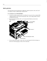
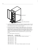
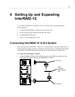
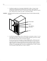
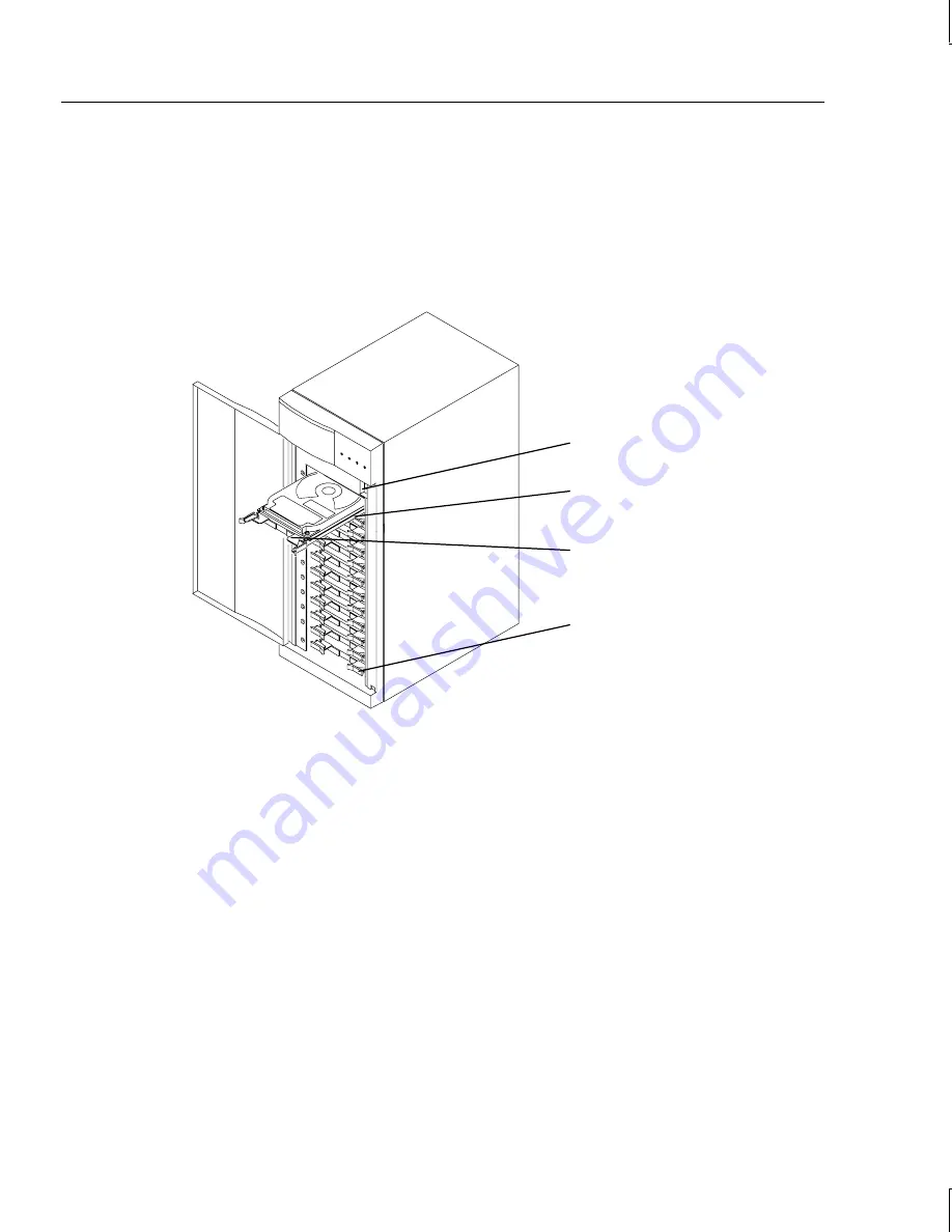
3. Install the boot disk drives in the primary InterRAID-12 cabinet. To insert a drive,
extend the drive latching clips and slide the drive into the slot. Push between the
latching clips until the drive connects. Close the drive latching clips until they snap into
place, locking the drive into the slot. Refer to the following figure.
CAUTION
Carefully insert the disk drives to avoid damaging the Single Connector Attachment (SCA)
connector.
4. Install the remaining RAID disk drives without labels into the primary cabinet. You can
install them in any order as long as the slots are filled sequentially upward (for example,
do not install drives in slots 5 and 7, leaving slot 6 empty).
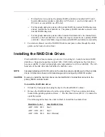
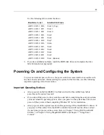
If necessary, fill in the label information for each RAID disk drive. Refer to the Drive
Labeling instruction sheet. The disk drive label has blank spaces for you to apply the
appropriate numbers to indicate the RAID controller board number (ADP X), channel
number (CHN Y), and SCSI ID number (ID Z). In the table below, Intergraph reserves
SCSI ID 3 for the entire disk array. The lower six RAID disk drives connect to channel
0, and the upper six RAID disk drives connect to channel 1.
Power Switch
Drive Latching
Clip (Open)
Slot 12
Slot 1
Summary of Contents for InterRAID-12
Page 1: ...InterRAID Hardware User s Guide January 1997 DHA018210 ...
Page 4: ......
Page 121: ...106 ...
Page 157: ...142 ...
Page 163: ...148 ...
Page 171: ...156 ...

