126
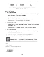
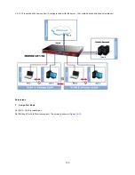
VLAN 2: Port-1, Port-2 and Port-3
VLAN 3: Port-4, Port-5 and Port-6
VLAN 1: All other ports – Port-7~Port-24
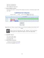
3. Remove VLAN Member for VLAN 1:
Remember to remove the Port 1 – Port 6 from VLAN 1 membership, since the Port 1 – Port 6 had been assigned to VLAN
2 and VLAN 3.
Figure 4-6-9
Add new VLAN group, assign VLAN members for VLAN 2 and VLAN 3 and Remove Specify Ports from VLAN 1
Member
It’s import to remove the VLAN members from VLAN 1 configuration. Or the ports would become
overlap setting. (About the overlapped VLAN configuration, see next VLAN configure sample)
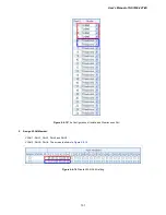
4. Assign PVID for each port:
Port-1, Port-2 and Port-3 : PVID=
2
Port-4, Port-5 and Port-6 : PVID=
3
Port-7~Port-24: PVID=
1
5. Enable VLAN Tag for specific ports
Link Type:
Port-3
(VLAN-2) and
Port-6
(VLAN-3)
The Per Port VLAN configuration in
Figure 4-6-10
.
Summary of Contents for IFS NS3550-24T/4S
Page 1: ...P N 1072569 REV 00 05 ISS 11OCT12 IFS NS3550 24T 4S User Manual ...
Page 37: ...User s Manual of NS3550 24T 4S 37 ...
Page 96: ...96 Figure 4 4 6 Port Mirror Configuration Page Screenshot ...
Page 127: ...User s Manual of NS3550 24T 4S 127 Figure 4 6 10 Port 1 Port 6 VLAN Configuration ...
Page 184: ...184 Figure 4 9 14 Voice VLAN Configuration Page Screenshot ...
Page 204: ...204 Figure 4 11 4 Network Access Server Configuration Page Screenshot ...
Page 234: ...234 Figure 4 12 1 Port Limit Control Configuration Overview Page Screenshot ...
Page 250: ...250 Click to undo any changes made locally and revert to previously saved values ...
Page 297: ...User s Manual of NS3550 24T 4S 297 ...
Page 388: ...388 Example Show RADIUS statistics SWITCH security aaa statistics ...
Page 410: ...410 Parameters vid VLAN ID 1 4095 Default Setting disable ...


