Chapter 2: Installation
26
NS3552-8P-2S-V2 User Manual
Installing the industrial managed switch
This section describes how to install and make connections to the industrial managed
switch. Read the following topics and perform the procedures in the order presented.
Caution:
When installing the industrial managed switch, ensure a clearance of two
inches at the top and bottom of the device to allow for proper cooling.
Installation steps
To install the industrial managed switch on a desktop or shelf:
1. Unpack the industrial managed switch
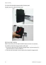
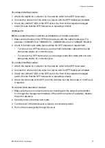
2. Ensure that the DIN-Rail is screwed onto the industrial managed switch. If the DIN-
rail is not screwed on, please refer to the DIN-rail mounting section for DIN-rail
installation. To wall-mount the industrial managed switch, please refer to the wall
mount plate mounting section for wall-mount plate installation.
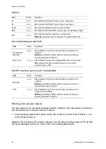
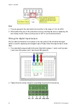
3. Power on the industrial managed switch. please refer to the wiring the power inputs
section for information about how to wire the power. The power LED on the
industrial managed switch illuminates. Refer to the LED Indicators section for
information about LED functionality.
4. Prepare the twisted-pair, straight-through Category 5 cable for Ethernet connection.
5. Insert one side of RJ45 cable (category 5) into the industrial managed switch
Ethernet port (RJ45 port) and the other side to the network device’s Ethernet (RJ45)
port (e.g., switch PC or server). The UTP port (RJ45) LED on the industrial
managed switch illuminates when the cable is connected with the network device.
Refer to the LED Indicators section for information about LED functionality.
Note:
Ensure that the connected network devices support MDI/MDI-X. If they do not
support this, use the crossover Category 5 cable.
6. When all connections are set and all LED lights appear normal, the installation is
complete.
Mounting
There are two methods to mount the industrial managed switch: DIN-rail mounting and
wall-mount plate mounting. Please read the following topics and perform the
procedures in the order presented.
Summary of Contents for NS3552-8P-2S-V2
Page 1: ...NS3552 8P 2S V2 User Manual P N 1073552 EN REV B ISS 25JAN19 ...
Page 41: ...Chapter 3 Switch management NS3552 8P 2S V2 User Manual 39 ...
Page 73: ...Chapter 4 Web configuration NS3552 8P 2S V2 User Manual 71 ...
Page 147: ...Chapter 4 Web configuration NS3552 8P 2S V2 User Manual 145 ...
Page 511: ......


