111
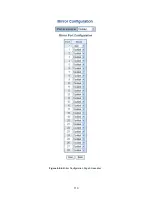
The page includes the following fields:
Object
Description
Port to mirror on
Port to mirror
also known as the
mirror port
. Frames from ports that have either source
(rx) or destination (tx) mirroring enabled are mirrored on this port.
Disabled
disables
mirroring.
Port
The logical port for the settings contained in the same row,
*
means selection of all ports
of Managed Switch.
Select mirror mode.
Rx only
: Frames received at this port are mirrored to the mirroring port.
Frames transmitted are not mirrored.
Tx only
:
Frames transmitted from this port are mirrored to the mirroring port.
Frames received are not mirrored.
Disabled
:
Neither frames transmitted nor frames received are mirrored.
Mode
Both
:
Frames received and frames transmitted are mirrored to the mirror port.
For a given port, a frame is only transmitted once. It is therefore not possible to mirror Tx frames on
the
mirror port
. Because of this,
mode
for the selected mirror port is limited to
Disabled
or
Rx only
.
Buttons
: Click to save changes.
: Click to undo any changes made locally and revert to previously saved values.
4.5 Link Aggregation
Port Aggregation optimizes port usage by linking a group of ports together to form a single Link Aggregated Groups (LAGs). Port
Aggregation multiplies the bandwidth between the devices, increases port flexibility, and provides link redundancy.
Each LAG is composed of ports of the same speed, set to full-duplex operations. Ports in a LAG, can be of different media types
(UTP/Fiber, or different fiber types), provided they operate at the same speed.
Aggregated Links can be assigned manually (
Port Trunk
) or automatically by enabling Link Aggregation Control Protocol (
LACP
)
on the relevant links.
Summary of Contents for NS4750-24S-4T-4X
Page 1: ...NS4750 24S 4T 4X User Manual P N 1702826 REV 00 01 ISS 14JUL14 ...
Page 56: ...56 Figure 4 2 7 Privilege Levels Configuration Page Screenshot ...
Page 110: ...110 Figure 4 4 6 Mirror Configuration Page Screenshot ...
Page 117: ...117 Figure 4 5 4 LACP Port Configuration Page Screenshot ...
Page 174: ...174 Figure 4 7 10 MST1 MSTI Port Configuration Page Screenshot ...
Page 180: ...180 Figure 4 8 2 Multicast Flooding ...
Page 249: ...249 Figure 4 9 18 Voice VLAN Configuration Page Screenshot ...
Page 271: ...271 Counter Counts the number of frames that match this ACE ...
Page 281: ...281 Figure 4 11 4 Network Access Server Configuration Page Screenshot ...
Page 315: ...315 ...
Page 328: ...328 ...
Page 335: ...335 ...
Page 346: ...346 Figure 4 14 1 LLDP Configuration Page Screenshot ...
Page 350: ...350 Figure 4 14 2 LLDP MED Configuration Page Screenshot ...
Page 372: ...372 Figure 4 16 1 Loop Protection Configuration Page Screenshot ...

