118
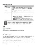
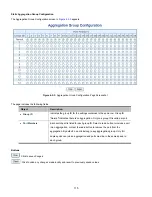
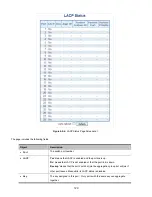
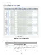
The page includes the following fields:
Object
Description
Port
The switch port number,
*
means selection of all ports of Managed Switch.
LACP Enabled
Controls whether LACP is enabled on this switch port. LACP will form an
aggregation when 2 or more ports are connected to the same partner. LACP can
form max 12 LLAGs per switch and 2 GLAGs per stack.
Key
The Key value incurred by the port range 1-65535. The Auto setting will set the
key as appropriate by the physical link speed, 10Mb = 1, 100Mb = 2, 1Gb = 3.
Using the Specific setting, a user-defined value can be entered. Ports with the
same Key value can participate in the same aggregation group, while ports with
different keys cannot.
The default setting is “
Auto
”
Role
The Role shows the LACP activity status. The Active will transmit LACP packets
each second; while Passive will wait for a LACP packet from a partner (speak if
spoken to).
Timeout
The Timeout controls the period between BPDU transmissions. Fast will transmit
LACP packets each second, while Slow will wait for 30 seconds before sending a
LACP packet
.
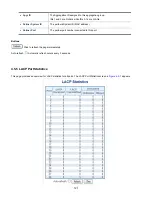
Partner Priority
The
Prio
controls the priority of the port. If the LACP partner wants to form a
larger group than is supported by this device then this parameter will control
which ports will be active and which ports will be in a backup role. Lower number
means greater priority.
Buttons
: Click to save changes.
: Click to undo any changes made locally and revert to previously saved values.
4.5.3 LACP System Status
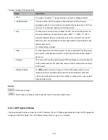
This page provides a status overview for all LACP instances. The LACP Status page display the current LACP aggregation
Groups and LACP Port status. The LACP System Status screen in
Figure 4-5-5
appears.
Summary of Contents for NS4750-24S-4T-4X
Page 1: ...NS4750 24S 4T 4X User Manual P N 1702826 REV 00 01 ISS 14JUL14 ...
Page 56: ...56 Figure 4 2 7 Privilege Levels Configuration Page Screenshot ...
Page 110: ...110 Figure 4 4 6 Mirror Configuration Page Screenshot ...
Page 117: ...117 Figure 4 5 4 LACP Port Configuration Page Screenshot ...
Page 174: ...174 Figure 4 7 10 MST1 MSTI Port Configuration Page Screenshot ...
Page 180: ...180 Figure 4 8 2 Multicast Flooding ...
Page 249: ...249 Figure 4 9 18 Voice VLAN Configuration Page Screenshot ...
Page 271: ...271 Counter Counts the number of frames that match this ACE ...
Page 281: ...281 Figure 4 11 4 Network Access Server Configuration Page Screenshot ...
Page 315: ...315 ...
Page 328: ...328 ...
Page 335: ...335 ...
Page 346: ...346 Figure 4 14 1 LLDP Configuration Page Screenshot ...
Page 350: ...350 Figure 4 14 2 LLDP MED Configuration Page Screenshot ...
Page 372: ...372 Figure 4 16 1 Loop Protection Configuration Page Screenshot ...


