125
Some relevant terms:
-
Tagging
- The act of putting 802.1Q VLAN information into the header of a packet.
-
Untagging
- The act of stripping 802.1Q VLAN information out of the packet header.
■
802.1Q VLAN Tags
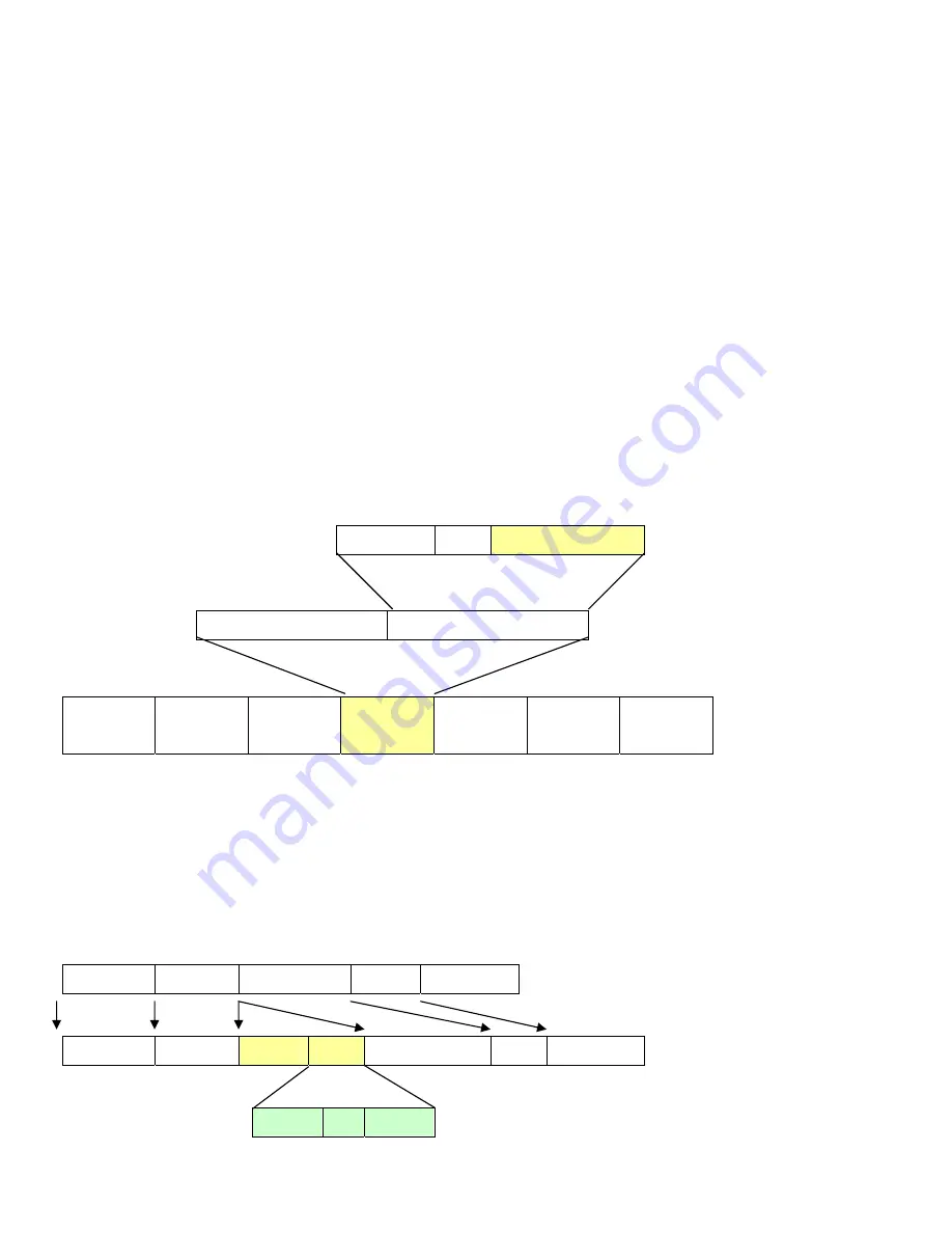
The figure below shows the 802.1Q VLAN tag. There are four additional octets inserted after the source MAC address. Their
presence is indicated by a value of
0x8100
in the Ether Type field. When a packet's Ether Type field is equal to 0x8100, the packet
carries the IEEE 802.1Q/802.1p tag. The tag is contained in the following two octets and consists of 3 bits of user priority, 1 bit of
Canonical Format Identifier (CFI - used for encapsulating Token Ring packets so they can be carried across Ethernet backbones),
and 12 bits of
VLAN ID (VID)
. The 3 bits of user priority are used by 802.1p. The VID is the VLAN identifier and is used by the
802.1Q standard. Because the VID is 12 bits long, 4094 unique VLAN can be identified.
The tag is inserted into the packet header making the entire packet longer by 4 octets. All of the information originally contained in
the packet is retained.
802.1Q Tag
User Priority
CFI
VLAN ID (VID)
3 bits
1 bits
12 bits
TPID (Tag Protocol Identifier)
TCI (Tag Control Information)
2
bytes 2
bytes
Preamble Destination
Address
Source
Address
VLAN TAG
Ethernet
Type
Data FCS
6 bytes
6 bytes
4 bytes
2 bytes
46-1500 bytes
4 bytes
The Ether Type and VLAN ID are inserted after the MAC source address, but before the original Ether Type/Length or Logical Link
Control. Because the packet is now a bit longer than it was originally, the Cyclic Redundancy Check (CRC) must be recalculated.
Adding an IEEE802.1Q Tag
Dest. Addr.
Src. Addr.
Length/E. type
Data
Old CRC
Dest. Addr.
Src. Addr.
E. type
Tag
Length/E. type
Data
New CRC
Priority
CFI
VLAN ID
Original Ethernet
New Tagged Packet
Summary of Contents for NS4750-24S-4T-4X
Page 1: ...NS4750 24S 4T 4X User Manual P N 1702826 REV 00 01 ISS 14JUL14 ...
Page 56: ...56 Figure 4 2 7 Privilege Levels Configuration Page Screenshot ...
Page 110: ...110 Figure 4 4 6 Mirror Configuration Page Screenshot ...
Page 117: ...117 Figure 4 5 4 LACP Port Configuration Page Screenshot ...
Page 174: ...174 Figure 4 7 10 MST1 MSTI Port Configuration Page Screenshot ...
Page 180: ...180 Figure 4 8 2 Multicast Flooding ...
Page 249: ...249 Figure 4 9 18 Voice VLAN Configuration Page Screenshot ...
Page 271: ...271 Counter Counts the number of frames that match this ACE ...
Page 281: ...281 Figure 4 11 4 Network Access Server Configuration Page Screenshot ...
Page 315: ...315 ...
Page 328: ...328 ...
Page 335: ...335 ...
Page 346: ...346 Figure 4 14 1 LLDP Configuration Page Screenshot ...
Page 350: ...350 Figure 4 14 2 LLDP MED Configuration Page Screenshot ...
Page 372: ...372 Figure 4 16 1 Loop Protection Configuration Page Screenshot ...

