142
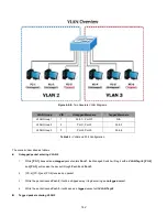
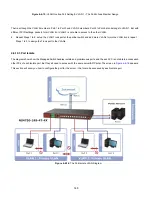
Figure 4-6-8:
Two Separate VLAN Diagrams
VLAN Group
VID
Untagged Members
Tagged Members
VLAN Group 1
1
Port-7 ~ Port-10
N/A
VLAN Group 2
2
Port-1,Port-2
Port-3
VLAN Group 3
3
Port-4,Port-5
Port-6
Table 4-1:
VLAN and Port Configuration
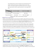
The scenario described as follows:
Untagged packet entering VLAN 2
1.
While
[PC-1]
transmit an
untagged
packet enters
Port-1
, the Managed Switch will tag it with a
VLAN Tag=2
.
[PC-2]
and
[PC-3]
will receive the packet through
Port-2
and
Port-3
.
2.
[PC-4],[PC-5] and [PC-6] received no packet.
3.
While the packet leaves
Port-2
, it will be stripped away it tag becoming an
untagged
packet.
4.
While the packet leaves
Port-3
, it will keep as a
tagged
packet with
VLAN Tag=2
.
Tagged packet entering VLAN 2
Summary of Contents for NS4750-24S-4T-4X
Page 1: ...NS4750 24S 4T 4X User Manual P N 1702826 REV 00 01 ISS 14JUL14 ...
Page 56: ...56 Figure 4 2 7 Privilege Levels Configuration Page Screenshot ...
Page 110: ...110 Figure 4 4 6 Mirror Configuration Page Screenshot ...
Page 117: ...117 Figure 4 5 4 LACP Port Configuration Page Screenshot ...
Page 174: ...174 Figure 4 7 10 MST1 MSTI Port Configuration Page Screenshot ...
Page 180: ...180 Figure 4 8 2 Multicast Flooding ...
Page 249: ...249 Figure 4 9 18 Voice VLAN Configuration Page Screenshot ...
Page 271: ...271 Counter Counts the number of frames that match this ACE ...
Page 281: ...281 Figure 4 11 4 Network Access Server Configuration Page Screenshot ...
Page 315: ...315 ...
Page 328: ...328 ...
Page 335: ...335 ...
Page 346: ...346 Figure 4 14 1 LLDP Configuration Page Screenshot ...
Page 350: ...350 Figure 4 14 2 LLDP MED Configuration Page Screenshot ...
Page 372: ...372 Figure 4 16 1 Loop Protection Configuration Page Screenshot ...

